Capacitance Decade Box
Capacitance boxes are a niche tool - certainly less useful than the resistance decade box in my last post - but I estimated that this would cost under $100, and it seemed like a fun project. It was! I'm not sure how much use I'll get out of it, though; maybe for tuning control loops or filters?
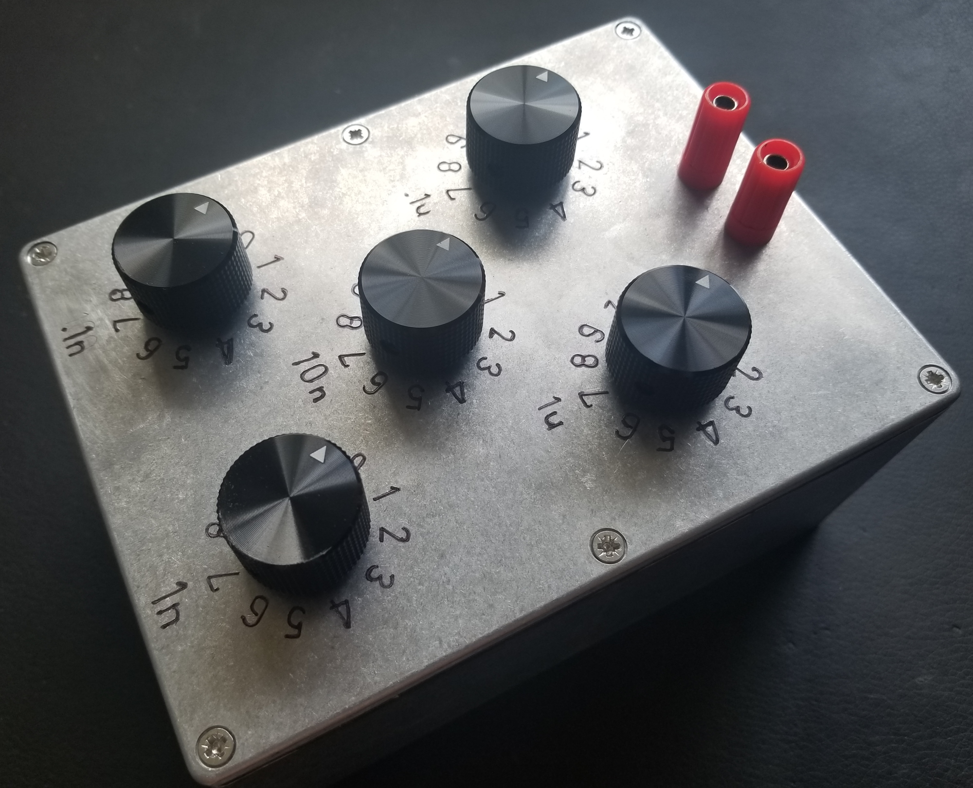
This box has 5 decades from 100pF to 1uF. The outer two decades are 5%; the inner three decades are 3%. The open-circuit capacitance is below one count on the lowest decade. All caps are polypropylene and rated to at least 400Vdc. This means the box can reach up to 11uF in 100pF steps with some really high quality, high voltage caps. It also means that this box is (theoretically) suitable for tuning mains filters!
Practical implementation of a capacitance box is a lot more complicated than a resistance box. Resistors can be connected in series and tapped with a rotary switch (see my last post). This isn't true for capacitors because capacitances do not sum in series. A naive approach would require an 11P11T rotary switch, or some more esoteric form of switch. Thumbwheel switches would be perfect for this application, but tragically they're either flimsy crap or quite expensive. I'm aiming for a "prosumer" niche with this project - it has to look nice without breaking the bank.
I found my solution in (and designed the entire project around) some 4P11T rotary switches available for a very reasonable price on aliexpress. It's impossible to overemphasize what a great value these switches are: $4.58 for an enormous, robust rotary switch with niche parameters. Each switch had to be disassembled to form the final assembly. While I failed to take any pictures of the switch construction, I did get a feeling for the build quality. The components are have mediocre quality control and are standardized such that they could form any pole/throw combination. They're probably assembled by slave labor. Considering that, they're impressively robust. There are no tiny springs or fragile plastic features like you'd find in a modern American design. There's nothing in these switches that would break if you threw it at the wall; this is your grandfather's switch!
Perhaps the only disadvantage of these switches in comparison to a typical western design (besides the size and vague sense of legal accountability) is that the contacts have tribological design dating from the '40s. Like your grandfather's switches, they'll pit and oxidize and after ten years in storage they'll probably have to be cycled a few times to make good electrical contact. At least the open switch frame will make it easy to apply contact cleaner when that day arrives.
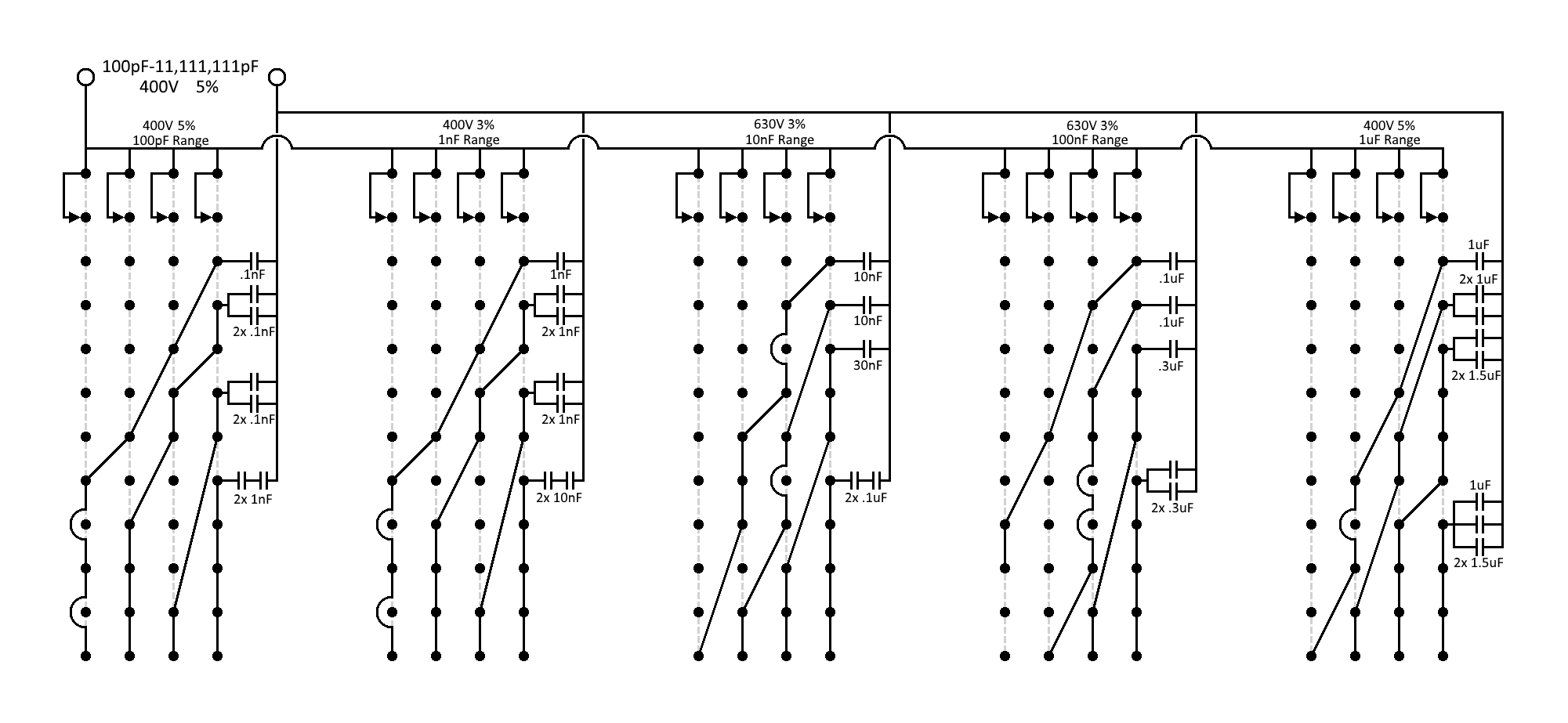
I digress. The 4P11T switches can be wired in a BCD-like configuration to create a decade from less than ten capacitors. BCD would imply four poles wired to 1/2/4/8uF capacitors respectively; this is essentially what I've done in the schematic. However, because BCD allows us to combine poles to reach values well beyond a decade (up to 15uF), we have some flexibility in the values we actually use. The decades have multiple unique configurations because film capacitor availability can be a crapshoot.
All switch poles are connected on one end forming the first terminal. All capacitors are joined on one lead forming the second terminal. The other ends of the poles and capacitors are connected in a complex matrix to achieve the right capacitance for any switch configuration.
Operation can be demonstrated by using the lowest decade as an example. In the 0th throw, the other end of each pole is floating (0pF). In the 1st throw, one pole is connected to a 100pF capacitor and the other poles are floating (totaling 100pF). In the 5th throw, one pole is floating, one pole is connected to a 100pF capacitor, and the two poles are connected separately to two distinct 200pF capacitors (totaling 500pF). So on and so forth. The "200pF" capacitors are actually two 100pF capacitors in series, again because polypropylene capacitors are not available in many values.
Finally the rotary switch can be seen in its glory. Too bad the lighting is poor and the switch mechanism isn't visible :(
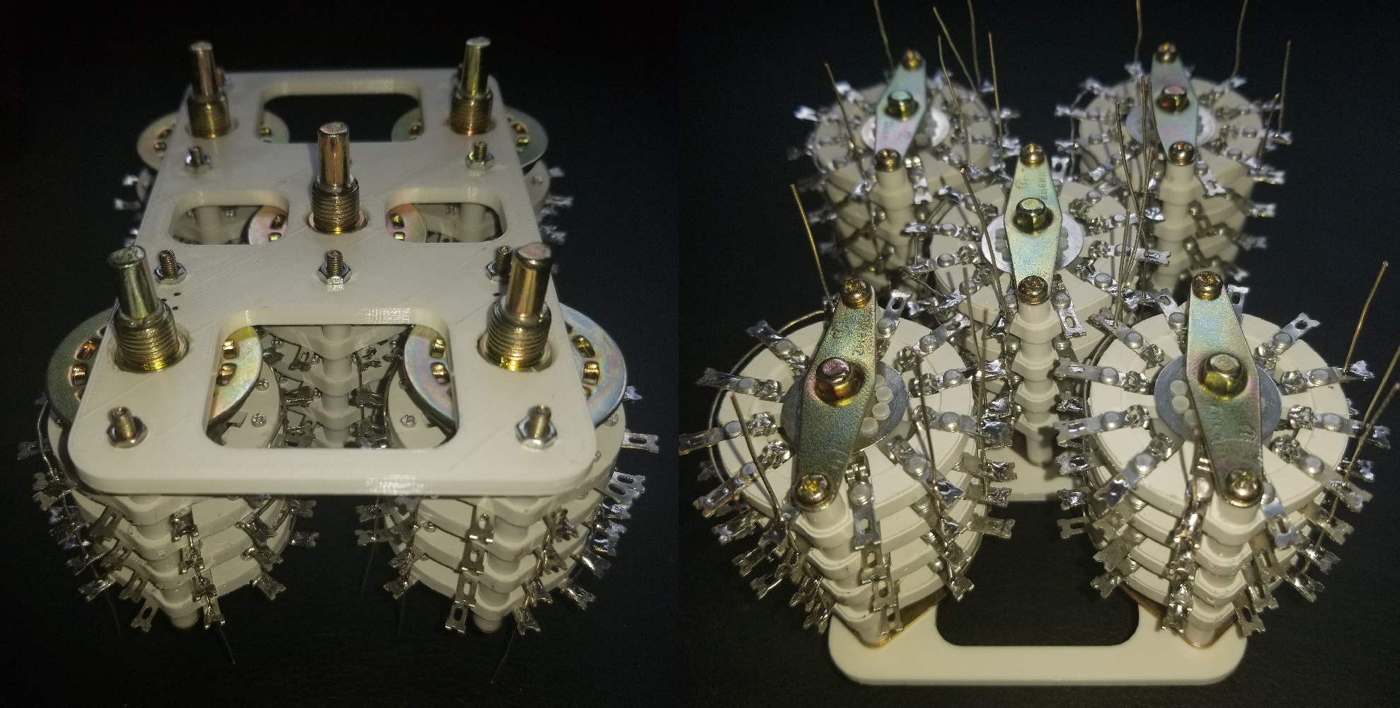
These switches are absolutely gargantuan, so they're packed together as tightly as possible. The switch contacts get daringly close to one another so a 3D printed frame is used to maintain clearance (and to provide anti-rotation). Assembling the switches in the frame required partially disassembling them, at which point they fell to pieces, so I got the full slave labor experience that was posited above.
Each switch here has already been soldered in the matrix configuration shown in the schematic. The visible protruding leads are future connection points for the capacitors. Wiring (and most soldering) was done as-assembled so clearance could be considered.
Two notes: The switch fasteners are pictured upside down; in the final assembly the bolt heads are recessed in the frame which looks nicer. A set of two printed flat brackets were added later to provide additional clearance control on the bottom.
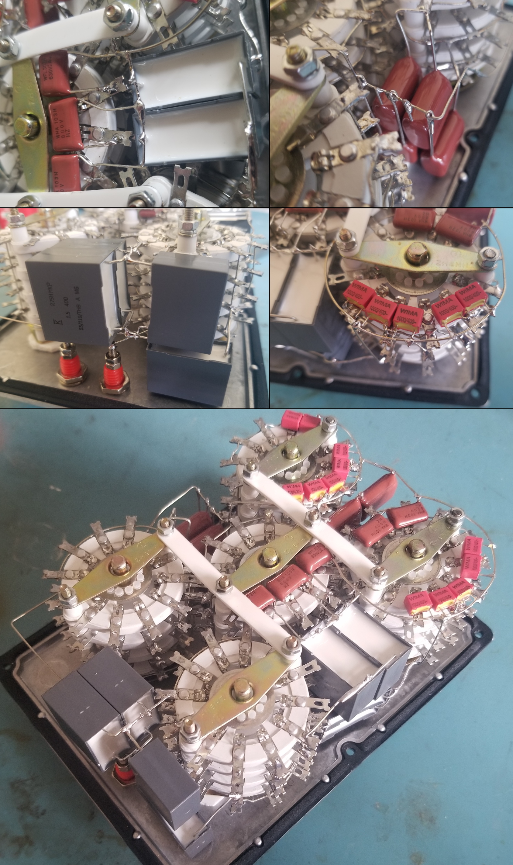
As before, these switches are huge and were packed into the smallest possible enclosure. Capacitors were almost an afterthought; they've been soldered freeform in the gaps between switches. I insist that the result is beautiful. And because the capacitors are free-floating, you could probably drop the box out a window without breaking any solder joints (you might cause a few transient shorts though; nothing is insulated).
I think the collage speaks for itself. This is art, folks.
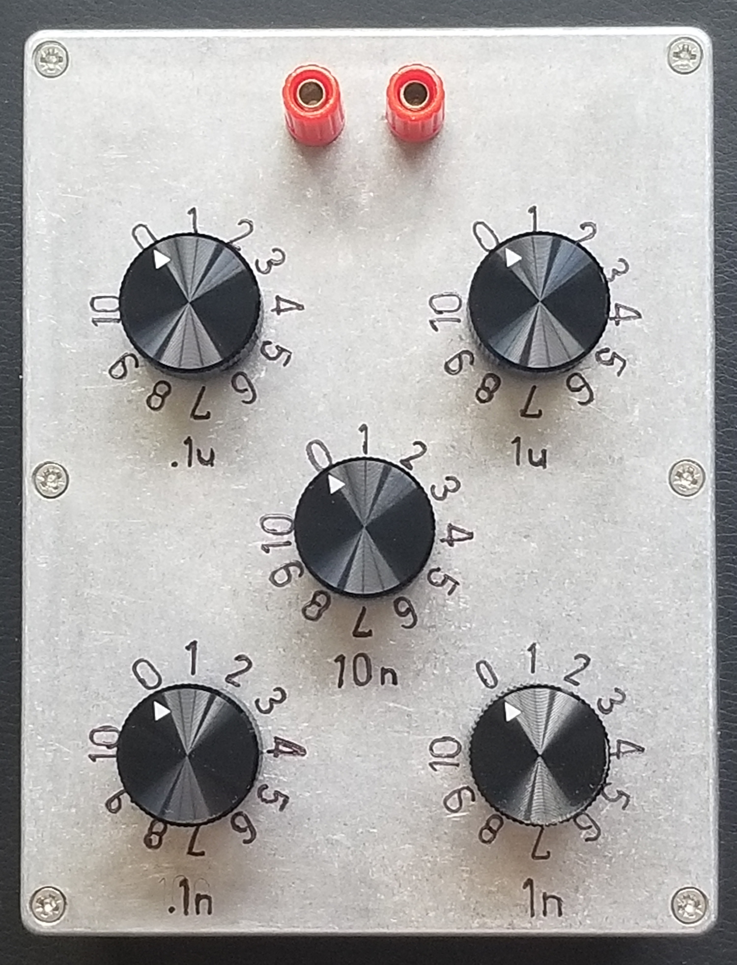
By far the worst part of the resistor decade box project was labeling the lid. For a few months this capacitance box was left bare and stuffed in a corner where I sheepishly averted my gaze. Finally, one day, my willpower returned and I tried a new approach. The markings pictured above are vibrapeened using a stencil, rather than stamped. All markings were made with the box fully assembled because the switches were used as a guide for the stencil, to keep all the numbers equidistant. This resulted in some kludges that less-than-artfully sanded off.
The embossings are filled in with permanent marker. There are surely more professional ways to add color (maybe some sort of urethane ink?) but the sharpie doesn't rub off whatsoever unless IPA is used.
I'm very happy with the result. The forged aluminum housings from Bud are always pretty, and the markings have a folksy freehand look.
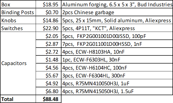
The final price did come in under $100. It's more than you'd spend on a whim, but I'm pretty sure you could package this thing in a 2U rack and sell it for $3500. I'll once again praise the Chinese switches not just for their own low price but also because they provided a ton of flexibility in capacitor selection, which I used to cost-optimize.
I would not recommend the binding posts (nor did I choose their color). Evidently you have to spend at least $5 on a binding post to get something decent. The knobs are nice but more expensive than I'd like; one of these days I'll get a lathe and make them myself.