Hakko-Powered Fume Extractor
Fume extractors are the sort of equipment that one often "forgets" to use. This is self-reinforcing. The more fumes you inhale, the less likely you are to remember to use your extractor next time. I chose to break this cycle and preserve my remaining brain cells. I've accomplished this by wiring my fume extractor to my iron such that both turn on simultaneously.
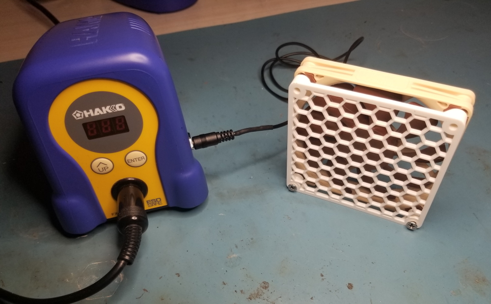
A keen eye will observe that I'm not using a real fume extractor. In fact it's just a Noctua fan. The perfectionist may opine that this won't work; doesn't the fan just recirculate the fumes? It does not. The extracted fumes presumably settle or disperse so widely as to be unnoticeable. This is perhaps imperfect but still leagues better than a dense cloud of smoke floating right into your face. In this lab we follow the Pareto principle.
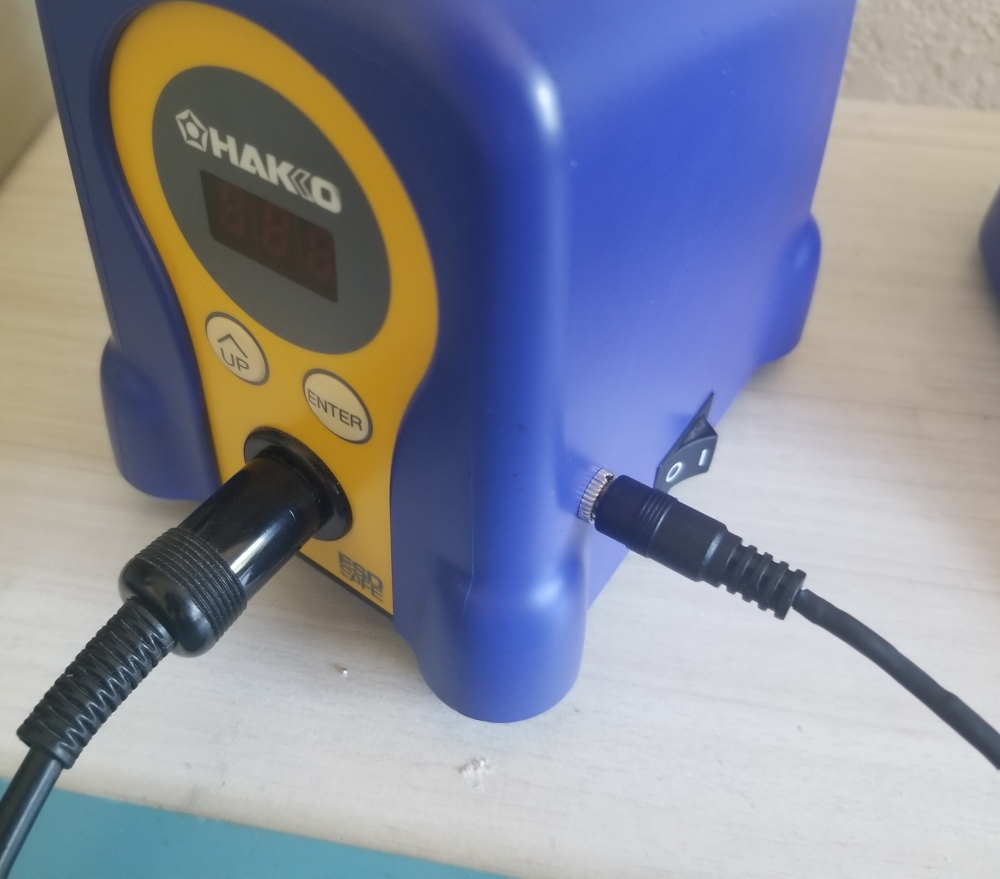
There's no clever engineering at play in this project. The Hakko iron's base station has a 28VAC transformer secondary winding. The power switch is on the primary side, so the transformer is cold unless the iron is switched on. I've tapped the transformer secondary, rectified it, regulated it, and fed it through a 3.5mm audio jack to power my fume extractor. Simple!
The relevant circuitry for the Hakko's control board is pictured above. It's honestly a little disappointing that it uses the same minimalistic topology as crappy mains triac dimmers. That's forgivable, as the transformer will filter out most mains transients. "Ground" as pictured is in fact the highest DC potential on the board; the control circuit runs on a negative supply to avoid driving the triac in its fourth quadrant. This is completely immaterial to my final solution but it was a relevant design consideration.
Our Noctua draws 120mA at 12V. This means that the transformer's rectified 40V (unloaded) is a pretty annoying voltage to work with. Direct linear regulation will dissipate over 3W which is undesirable because the Hakko's enclosure offers poor airflow and because its transformer is unlabeled, meaning I'd rather not draw an extra 3W when the fan only needs 1.4W itself. So I reverse-engineered the control board in the hopes that it would offer a lower voltage to tap. No luck; the bias supply is very weak and otherwise unsuitable in every way.
I considered using a capacitive dropper upstream of a linear regulator. This could be done with depolarized electrolytics that wouldn't need to be too large. Note however that electrolytics can span a 2:1 capacitance range over their working life (compare a new capacitor at +20% to an old capacitor that was -20% when new, and has degraded a further 20% per most datasheets' EOL figure). Designing a dropper requires ensuring adequate output voltage at load and minimum capacitance. At maximum capacitance the dropper's output voltage will be much higher. Downstream, our poor linear regulator will still be dissipating around 2W as it turns out. This defeats the purpose of the dropper. I could always hand-pick the capacitors, but that's just bad engineering.
There are other neat regulating topologies enabled by chips like Microchip's SR-10. These chips are all optimized for mains and aren't suitable at 28VAC. A discrete implementation would be cute but terrible on all metrics.
Woe is me. I gave up and used a buck converter. How inelegant! This drove me to design my own PCB; there aren't any tiny AC-DC modules on the market for this odd application.
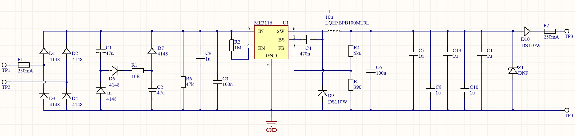
Finding a jellybean buck converter rated for 40V is kind of annoying. I make a best-effort to choose cheap and available ICs. This is counterproductive for prototyping; if I was working for pay I'd have wasted $300 in NRE to avoid buying some niche $8 chip from AD. Nonetheless I found an ME3116 which can be bought one-off for a mere $0.16.
The circuitry is mundane: a mains-frequency rectifier followed by a buck with some protection for the Noctua. The only notable oddity is that the bulk capacitors are wired in a power-factor-correcting topology. This isn't necessary, it's just belt-and-braces to minimize the extra stress we're putting on the Hakko's transformer.
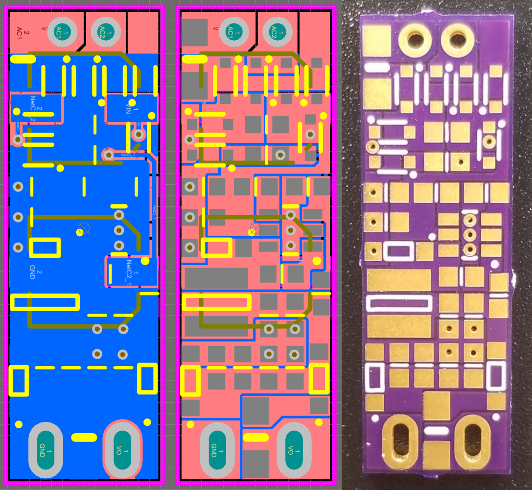
The board layout is also pretty mundane. It's not usually best-practice to place vias on SMD pads. I've never had the slightest issue with it though, and it let me condense the board. The only mistake here is that I misread the inductor dimensions so it's butting up against the buck diode.
Slots are provided on the board for direct mounting to a 3.5mm audio jack, which I used only because I have a lot sitting around. There's not a lot of free space in the enclosure so board size was important. This design fits nicely in a gap between the Hakko's control board and transformer.
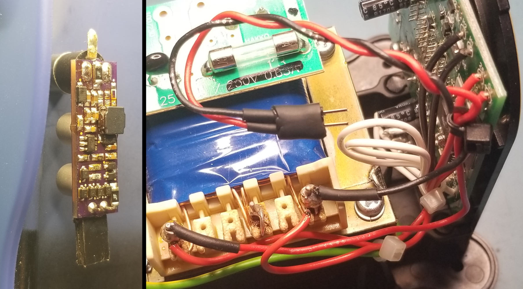
The inputs are wired directly from the transformer's secondary taps. I soldered them on using a hot air gun. It felt wrong to use the iron to solder itself, even if the tip is grounded and the secondary is galvanically isolated.
The final result looks pretty clean in my opinion. I used a straight audio plug because that's what I had available, but I've placed an order for a right-angle plug which will be less obtrusive.
DIY Humidistat
Some consumer gages are terrible. Foremost among this crowd are pressure gages, which have an odd habit of reading 10psi over. Cheap humidistats are equally dubious. This is one of those precious instances where DIY electronics beat consumer garbage in both cost and performance: a quality humidistat IC is much too expensive for mass production, but it's still only $3 on digikey!
I designed this project with intent to put it in a weatherproofed housing for use outdoors ("local" humidity reports are crap when the weather station is 30 miles away). I never got around to designing the housing, so it's an indoor sensor now.
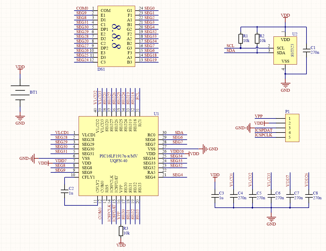
The schematic is as boring as it should be, to my credit. It's easy to succumb to the tendency to overengineer; dare ye not gaze upon the humidistat reference designs with peripheral circuitry galore.
I selected a PIC with an internal segmented LCD driver which allows for exceptionally low power consumption. A good CR2032 will last 18 months by my math. As it turns out, a shady aliexpress CR2032 will last 8 months.
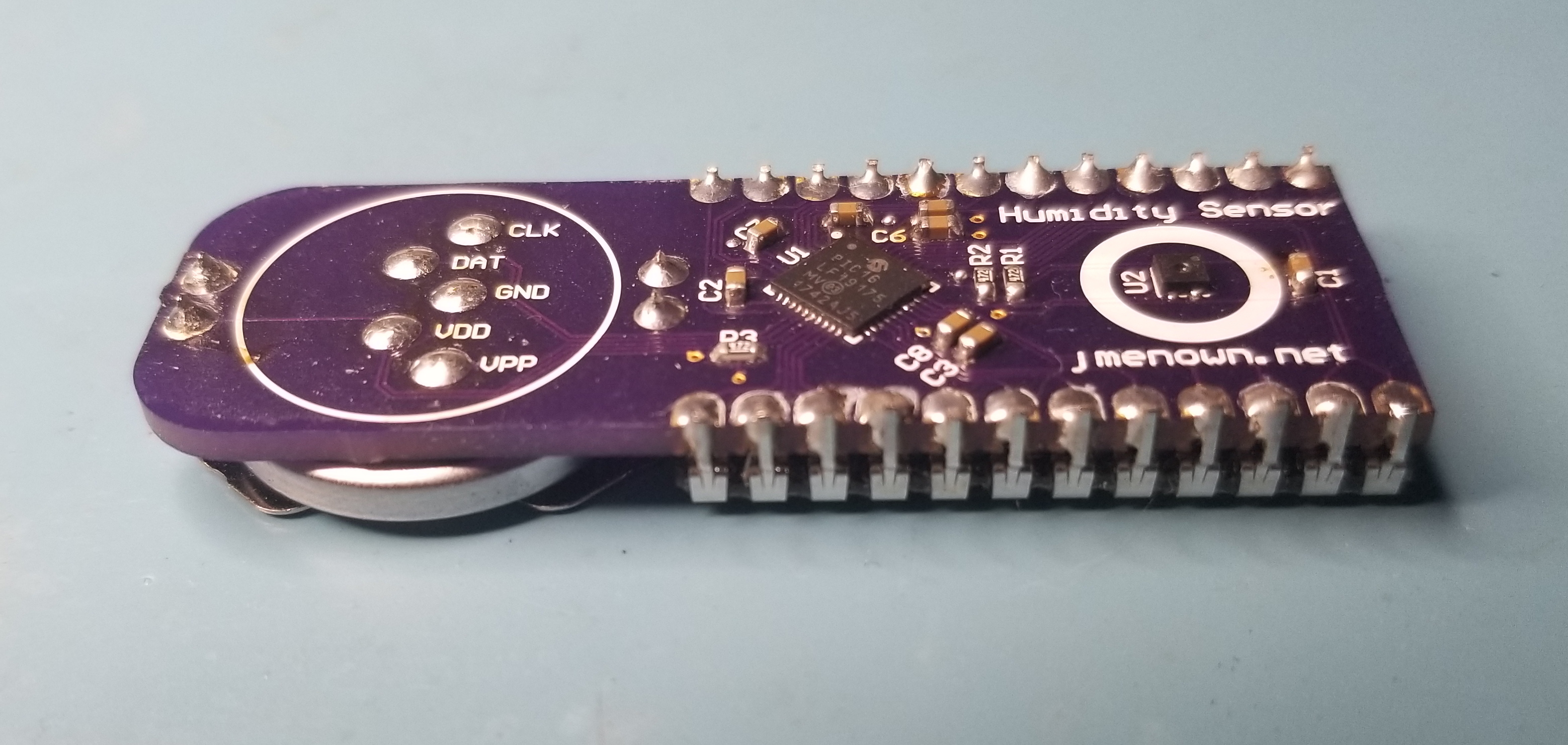
The SHTC3 humidistat IC is the cheapest on the market capable of ±2% relative humidity. This is the best technology can offer for small form factor humidistats. This chip is a mere $3 one-off, and you can pay much more without getting better performance. It integrates a ±0.2°C temperature sensor, which is nice. It's worth noting that these tolerances are only maintained in the middle region of the measurement band and they're only "typical", whatever the hell that means statistically. Worst-case midband humidity tolerance is ±3.5%. I don't hold this against the SHTC3, this is true for other offerings. Just another instance of datasheets trying to mislead you. It's not lying, really, just read the fine print!
The display is an aliexpress mystery special. The viewing angle and contrast are no worse than western displays. Segmented LCDs are actually kind of expensive, if you consider their ubiquity, so I'd probably avoid using them if not for the cheap Asian offerings. That would be a shame - they're much more elegant than a digital display.
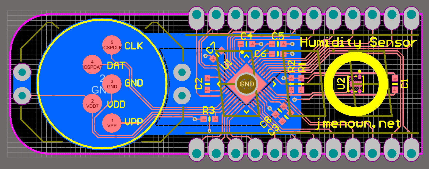
I'm proud of the board layout even if there's nothing really noteworthy about it. All traces are on top; the bottom layer is shared by concentric power and ground planes.
Note the large plated hole in the PIC's ground pad. This is an artifact of my QFN soldering method. I've stopped ordering solder paste stencils for my project as they're too expensive. Instead, I tin the bare pads with my iron, apply flux, place the QFN on its footprint, and reflow with hot air. This works exceptionally well (see the beautiful soldering in a picture below). The ground pad is an exception: it's easy to apply too much solder when tinning, meaning the QFN won't sit flat when reflowing. My solution is not to tin the ground pad until the rest of the pads are soldered. Then I can use the large plated hole to solder the ground pad from the bottom of the board. This sounds more convoluted than it is in practice.
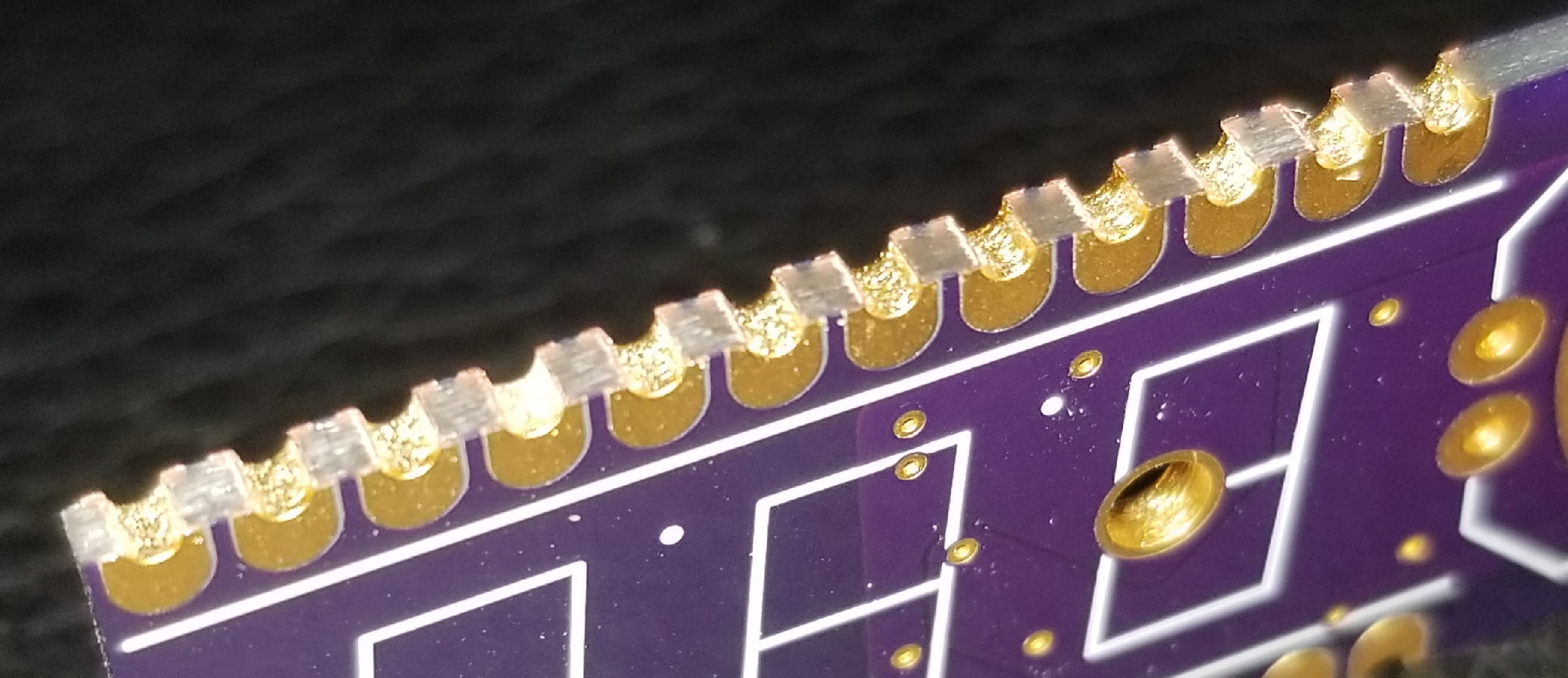
The board footprint is minimized by castellating the display's footprint. This is the first time I've ordered castellations from Oshpark and I'm satisfied with the result. The delivered boards had metal snags on the castellations that were removed by a side cutter with minimal effort.
I'm very happy with the result. A few of the display solder joints look cold in this picture but I think that's just the lighting. The SMD solder joints are gorgeous in my opinion. I wish I could replicate them on other projects!
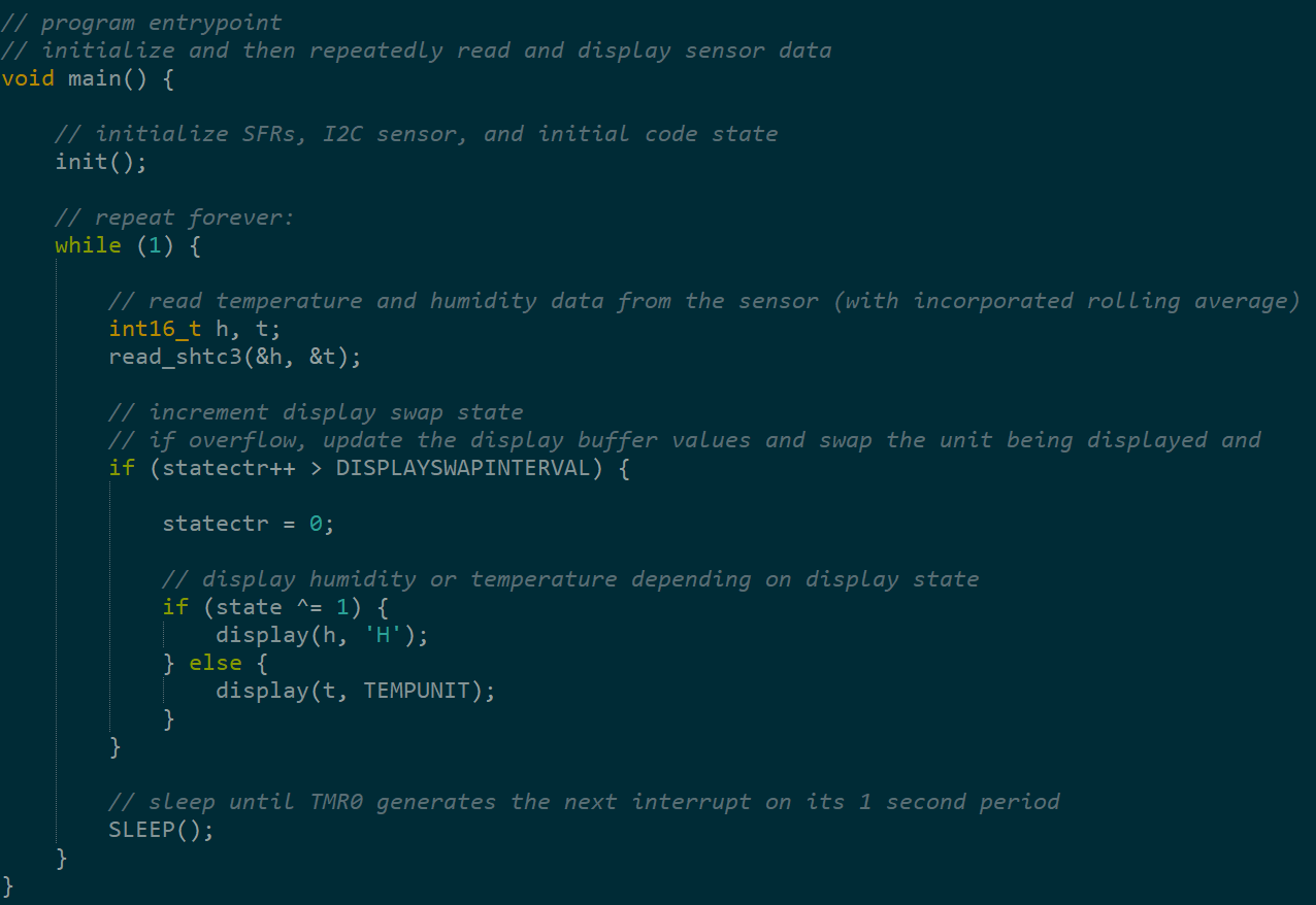
The PIC is programmed in C and compiled with XC8. The code is mundane so I've only added a snip of the main loop to convey the general idea. Humidistats are typically slow sensors so measurements are only taken once per second with 4X downsampling. Every four seconds the board will toggle between displaying temperature and humidity.
I have a vendetta against Git; it's by far the worst piece of software that I'm required to use. I'm familiar with it in a professional capacity but I absolutely refuse to spend a moment of my time uploading any personal projects to Github. The full code for this project will sadly remain a mystery until everyone adopts a less objectionable version control system.
DIY 18650 Battery Charger
This project cost under $5, by my estimate. It was pursued solely because I noticed a very cheap li-ion charger IC on Digikey, and tossed it in my cart. Each chip is soldered onto a miniature board from Oshpark. Because they charge by the square inch, with evidently no price floor, the boards were practically free as well. I felt kind of dirty ordering them.
A DIY 18650 charger does have its merits, despite the frivolous motivation. Chinese battery chargers are untrustworthy; this is a circumstance where some seriousness is warranted. These batteries hold a lot of Joules. That being said, proper Western chargers are kind of expensive. Is fire safety really worth $20? Nope. Hire me!
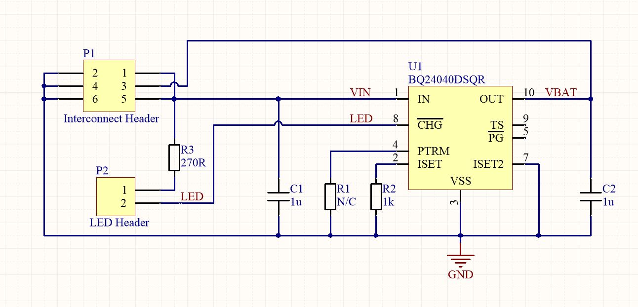
The BQ24040 charger chips aren't especially smart. Given they're from TI, though, I had no doubt that they'd work fine. A rectangular led is included for indication on charge termination. Two resistors are needed for LED current limiting and setting the 500mA peak charge current. The other passives are window dressing.
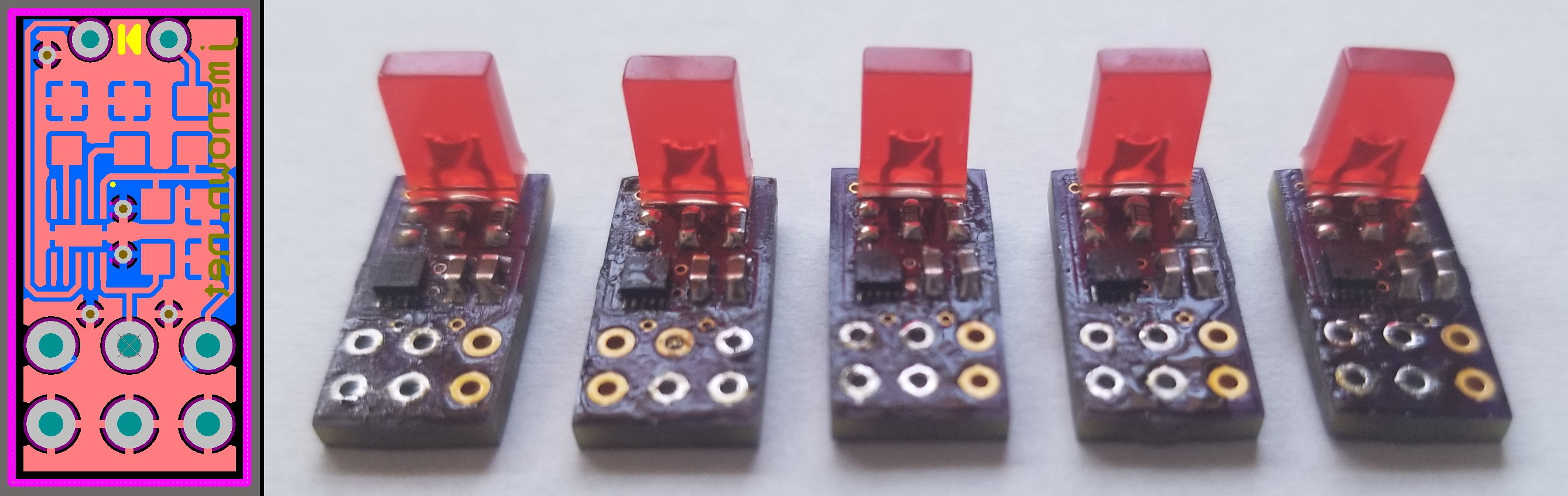
These chips are really small! This would not have been possible without a hot air gun. I did not order a solder paste stencil so I soldered these chips by pre-tinning the pads, applying flux, and then reflowing. The above picture was taken after I'd soldered some of the PTH headers for testing, so they look a bit ugly.
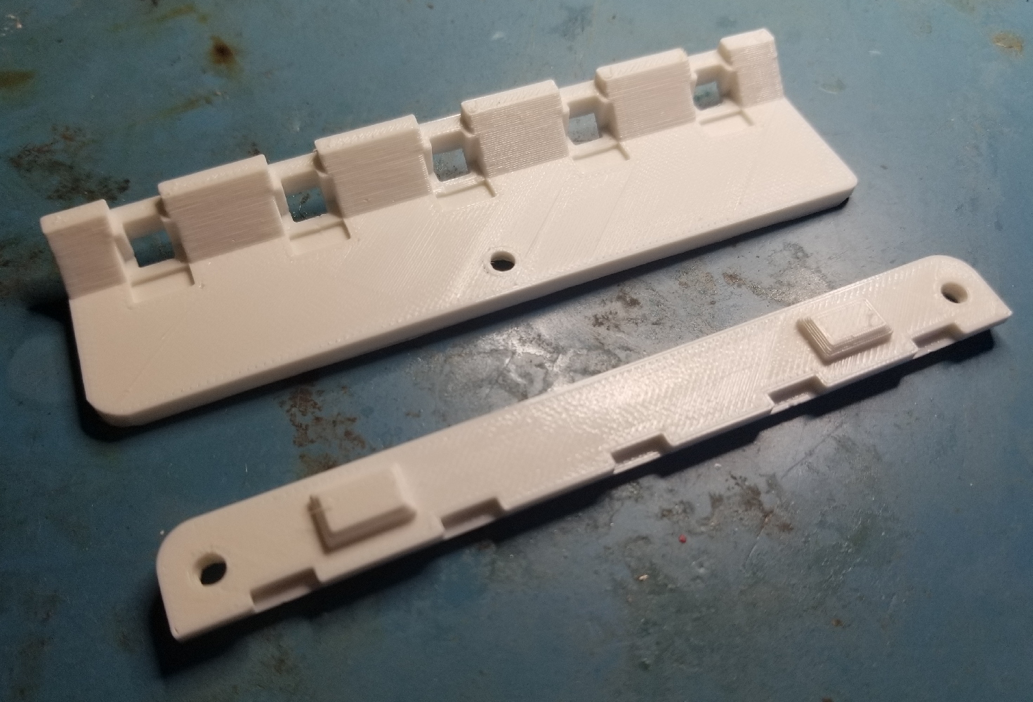
A housing was 3D printed in three pieces, as can be seen above and below.
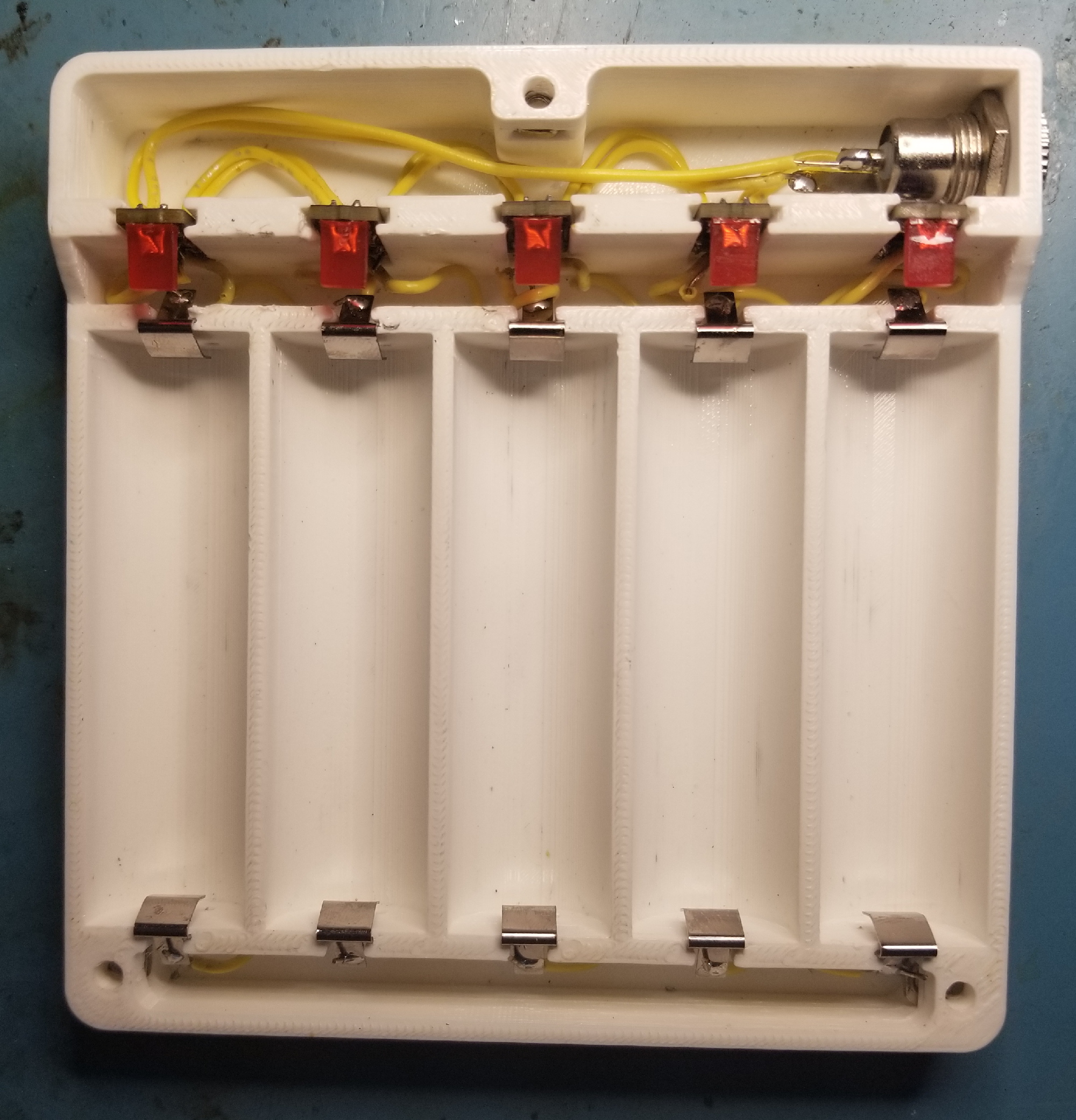
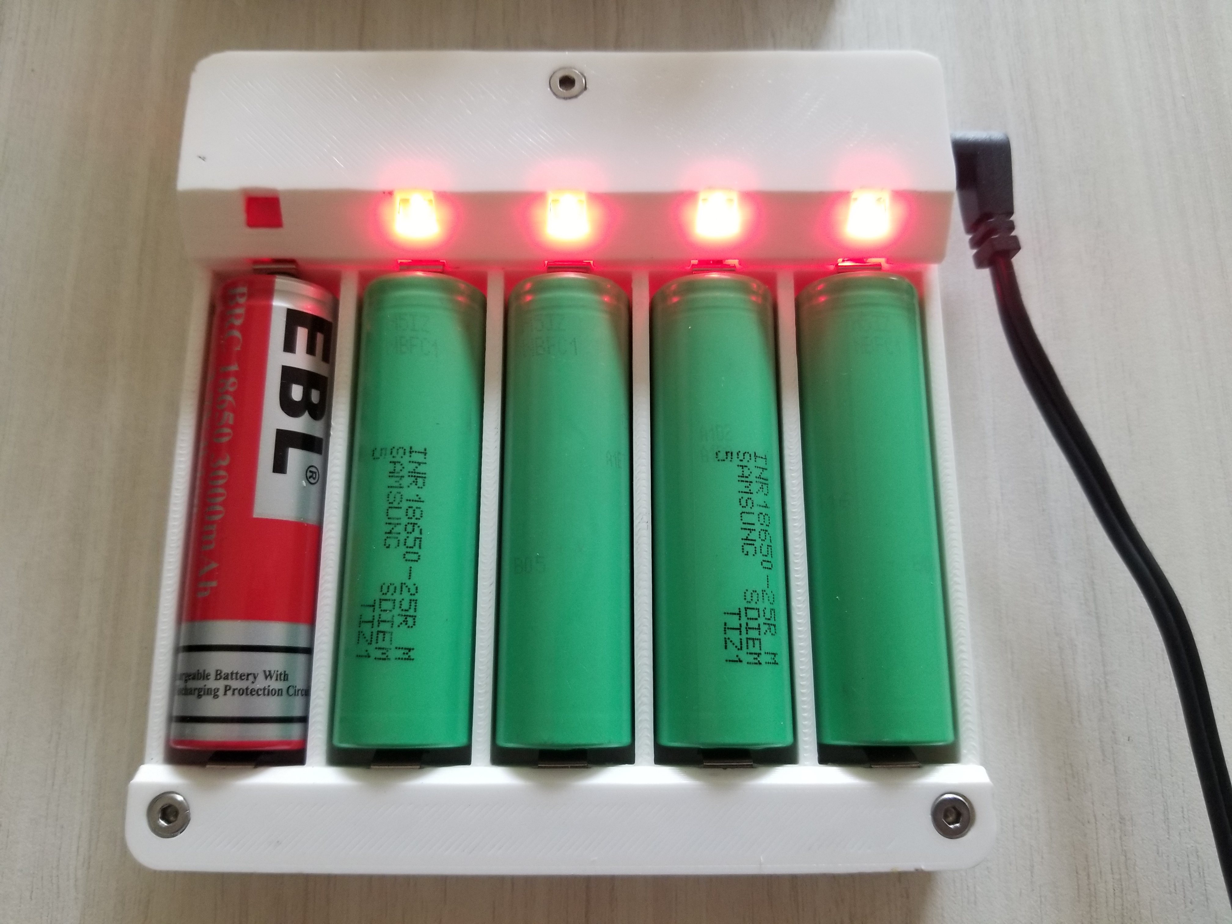
The main housing holds five charging bays with slots for snap-in leaf spring battery contacts. Behind the springs are fore and aft pockets for routing wiring. Wiring from the aft pocket gets fed into the forward pocket through holes underneath the charging bays. Adjacent to the forward pockets are slots for the charging boards. Each charging board has positive and negative terminal pads exposed to the forward pocket; wires from the leaf springs are soldered here.
Behind the charging boards there's a final pocket for routing wiring to a DC barrel jack on the side. Each board is daisy-chained, leading back to the DC jack. I've used a 5V/3A wall wart to power the assembly.
The result of all these pockets is an absolute mess of wiring. This was extremely difficult to solder and assemble; that's the price you pay for having five separate boards. All is well though: the pockets are hidden by two printed covers. No one has to know!
Capacitance Decade Box
Capacitance boxes are a niche tool - certainly less useful than the resistance decade box in my last post - but I estimated that this would cost under $100, and it seemed like a fun project. It was! I'm not sure how much use I'll get out of it, though; maybe for tuning control loops or filters?
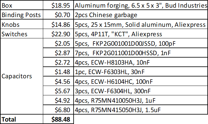
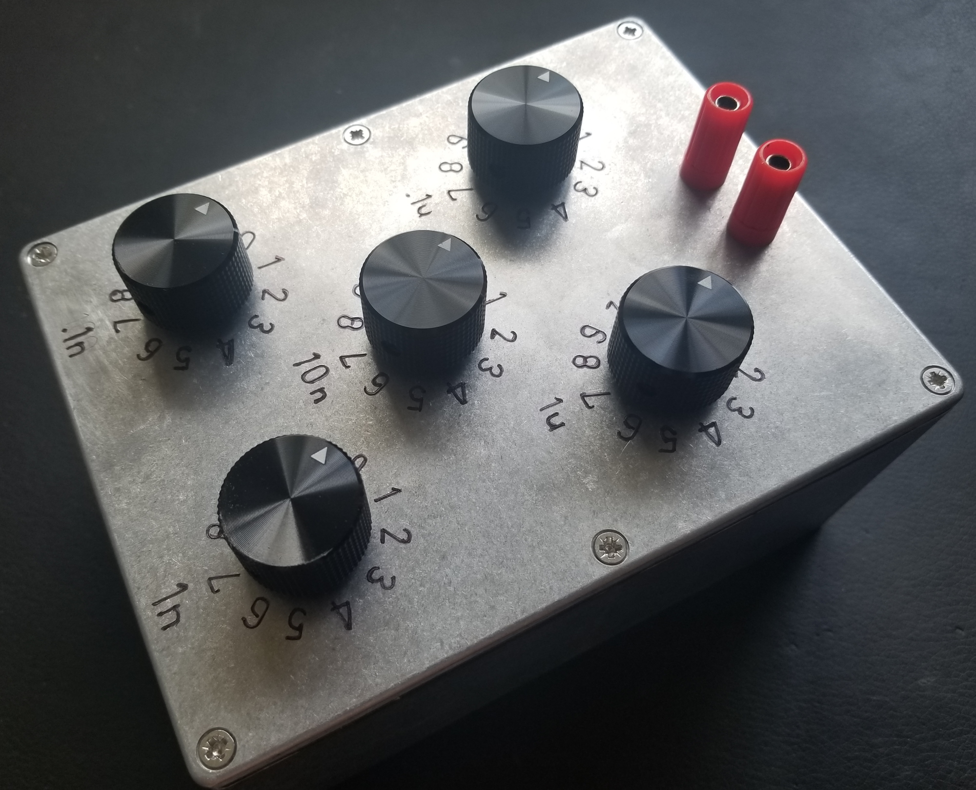
This box has 5 decades from 100pF to 1uF. The outer two decades are 5%; the inner three decades are 3%. The open-circuit capacitance is below one count on the lowest decade. All caps are polypropylene and rated to at least 400Vdc. This means the box can reach up to 11uF in 100pF steps with some really high quality, high voltage caps. It also means that this box is (theoretically) suitable for tuning mains filters!
Practical implementation of a capacitance box is a lot more complicated than a resistance box. Resistors can be connected in series and tapped with a rotary switch (see my last post). This isn't true for capacitors because capacitances do not sum in series. A naive approach would require an 11P11T rotary switch, or some more esoteric form of switch. Thumbwheel switches would be perfect for this application, but tragically they're either flimsy crap or quite expensive. I'm aiming for a "prosumer" niche with this project - it has to look nice without breaking the bank.
I found my solution in (and designed the entire project around) some 4P11T rotary switches available for a very reasonable price on aliexpress. It's impossible to overemphasize what a great value these switches are: $4.58 for an enormous, robust rotary switch with niche parameters. Each switch had to be disassembled to form the final assembly. While I failed to take any pictures of the switch construction, I did get a feeling for the build quality. The components are have mediocre quality control and are standardized such that they could form any pole/throw combination. They're probably assembled by slave labor. Considering that, they're impressively robust. There are no tiny springs or fragile plastic features like you'd find in a modern American design. There's nothing in these switches that would break if you threw it at the wall; this is your grandfather's switch!
Perhaps the only disadvantage of these switches in comparison to a typical western design (besides the size and vague sense of legal accountability) is that the contacts have tribological design dating from the '40s. Like your grandfather's switches, they'll pit and oxidize and after ten years in storage they'll probably have to be cycled a few times to make good electrical contact. At least the open switch frame will make it easy to apply contact cleaner when that day arrives.
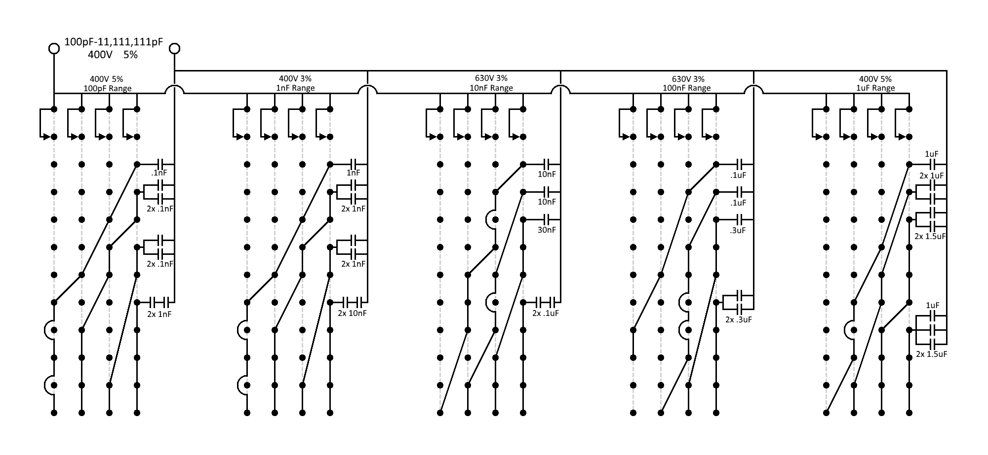
I digress. The 4P11T switches can be wired in a BCD-like configuration to create a decade from less than ten capacitors. BCD would imply four poles wired to 1/2/4/8uF capacitors respectively; this is essentially what I've done in the schematic. However, because BCD allows us to combine poles to reach values well beyond a decade (up to 15uF), we have some flexibility in the values we actually use. The decades have multiple unique configurations because film capacitor availability can be a crapshoot.
All switch poles are connected on one end forming the first terminal. All capacitors are joined on one lead forming the second terminal. The other ends of the poles and capacitors are connected in a complex matrix to achieve the right capacitance for any switch configuration.
Operation can be demonstrated by using the lowest decade as an example. In the 0th throw, the other end of each pole is floating (0pF). In the 1st throw, one pole is connected to a 100pF capacitor and the other poles are floating (totaling 100pF). In the 5th throw, one pole is floating, one pole is connected to a 100pF capacitor, and the two poles are connected separately to two distinct 200pF capacitors (totaling 500pF). So on and so forth. The "200pF" capacitors are actually two 100pF capacitors in series, again because polypropylene capacitors are not available in many values.
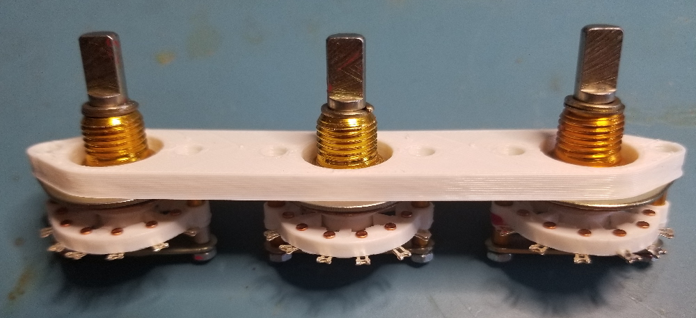
Finally the rotary switch can be seen in its glory. Too bad the lighting is poor and the switch mechanism isn't visible :(
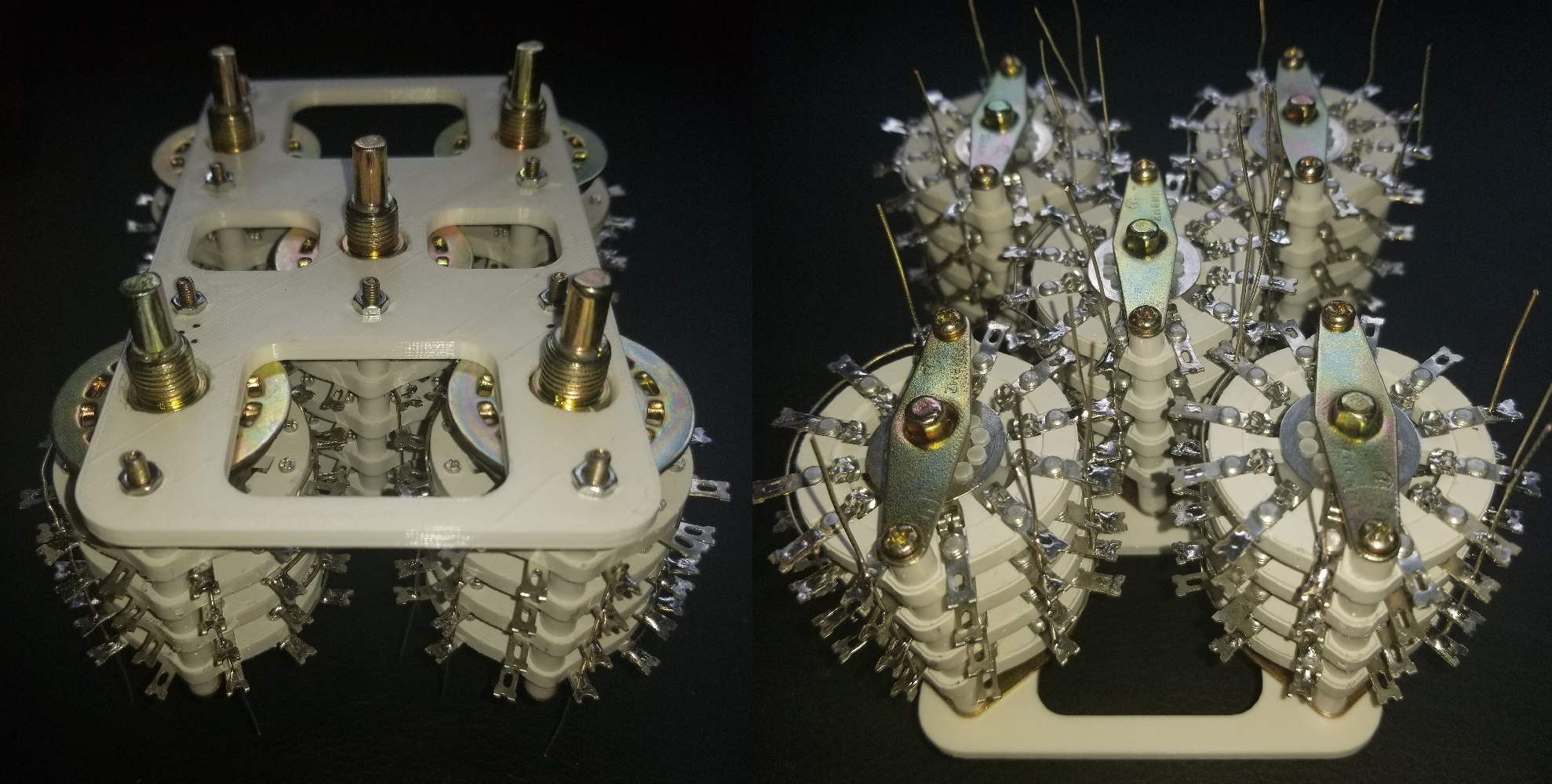
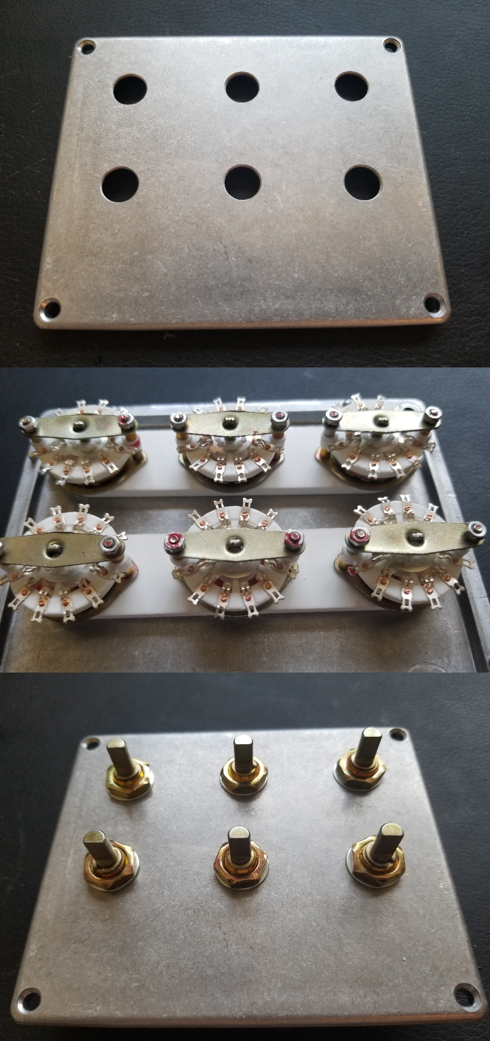
These switches are absolutely gargantuan, so they're packed together as tightly as possible. The switch contacts get daringly close to one another so a 3D printed frame is used to maintain clearance (and to provide anti-rotation). Assembling the switches in the frame required partially disassembling them, at which point they fell to pieces, so I got the full slave labor experience that was posited above.
Each switch here has already been soldered in the matrix configuration shown in the schematic. The visible protruding leads are future connection points for the capacitors. Wiring (and most soldering) was done as-assembled so clearance could be considered.
Two notes: The switch fasteners are pictured upside down; in the final assembly the bolt heads are recessed in the frame which looks nicer. A set of two printed flat brackets were added later to provide additional clearance control on the bottom.
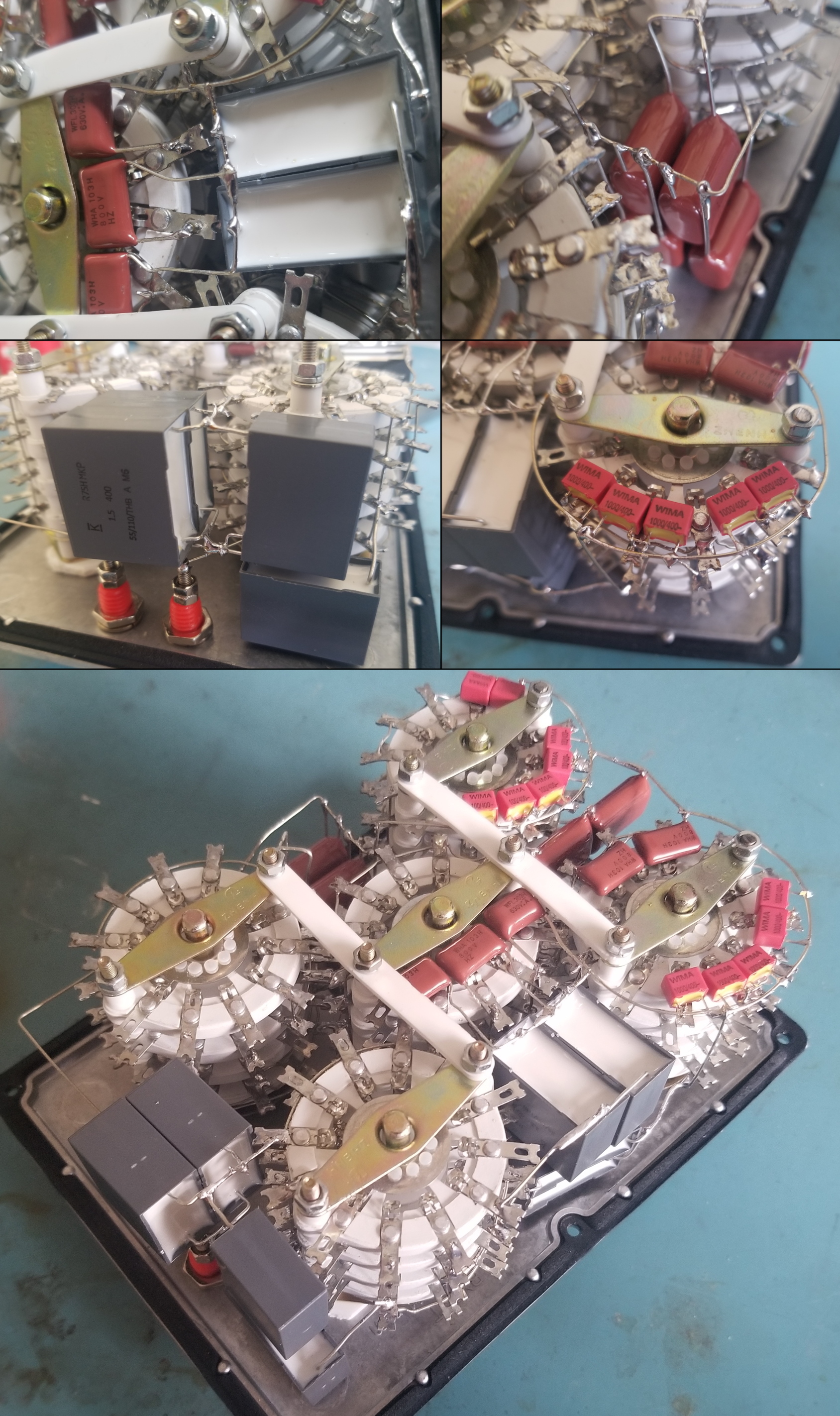
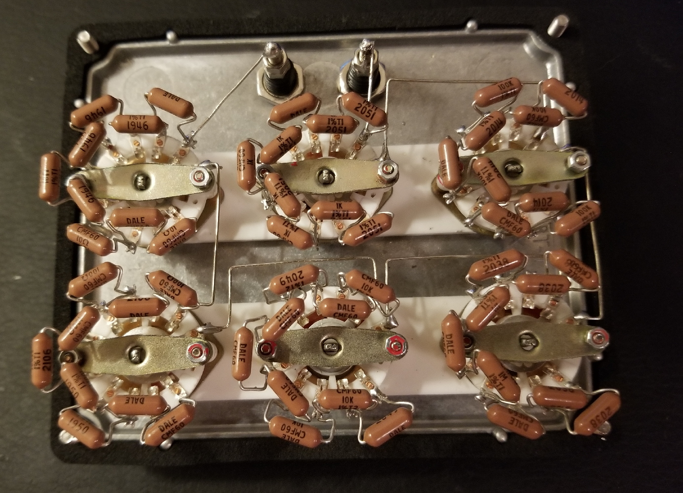
As before, these switches are huge and were packed into the smallest possible enclosure. Capacitors were almost an afterthought; they've been soldered freeform in the gaps between switches. I insist that the result is beautiful. And because the capacitors are free-floating, you could probably drop the box out a window without breaking any solder joints (you might cause a few transient shorts though; nothing is insulated).
I think the collage speaks for itself. This is art, folks.
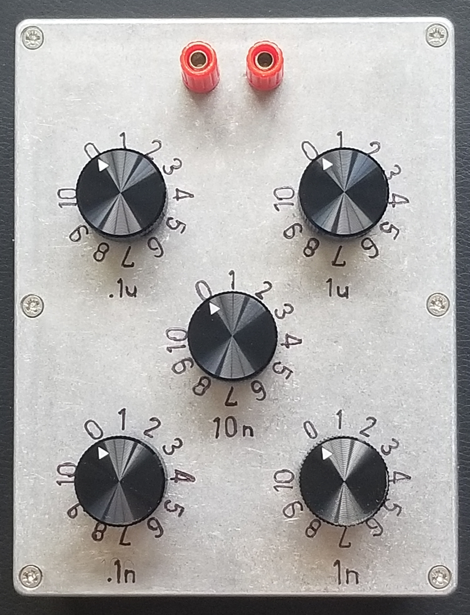
By far the worst part of the resistor decade box project was labeling the lid. For a few months this capacitance box was left bare and stuffed in a corner where I sheepishly averted my gaze. Finally, one day, my willpower returned and I tried a new approach. The markings pictured above are vibrapeened using a stencil, rather than stamped. All markings were made with the box fully assembled because the switches were used as a guide for the stencil, to keep all the numbers equidistant. This resulted in some kludges that less-than-artfully sanded off.
The embossings are filled in with permanent marker. There are surely more professional ways to add color (maybe some sort of urethane ink?) but the sharpie doesn't rub off whatsoever unless IPA is used.
I'm very happy with the result. The forged aluminum housings from Bud are always pretty, and the markings have a folksy freehand look.
The final price did come in under $100. It's more than you'd spend on a whim, but I'm pretty sure you could package this thing in a 2U rack and sell it for $3500. I'll once again praise the Chinese switches not just for their own low price but also because they provided a ton of flexibility in capacitor selection, which I used to cost-optimize.
I would not recommend the binding posts (nor did I choose their color). Evidently you have to spend at least $5 on a binding post to get something decent. The knobs are nice but more expensive than I'd like; one of these days I'll get a lathe and make them myself.
Resistance Decade Box
A resistor decade box is the sort of tool that you should build yourself - like a linear bench supply, or a welding table (I guess). In my case this project was long overdue. For years I've had to dig up a potentiometer any time a circuit needed tuning.
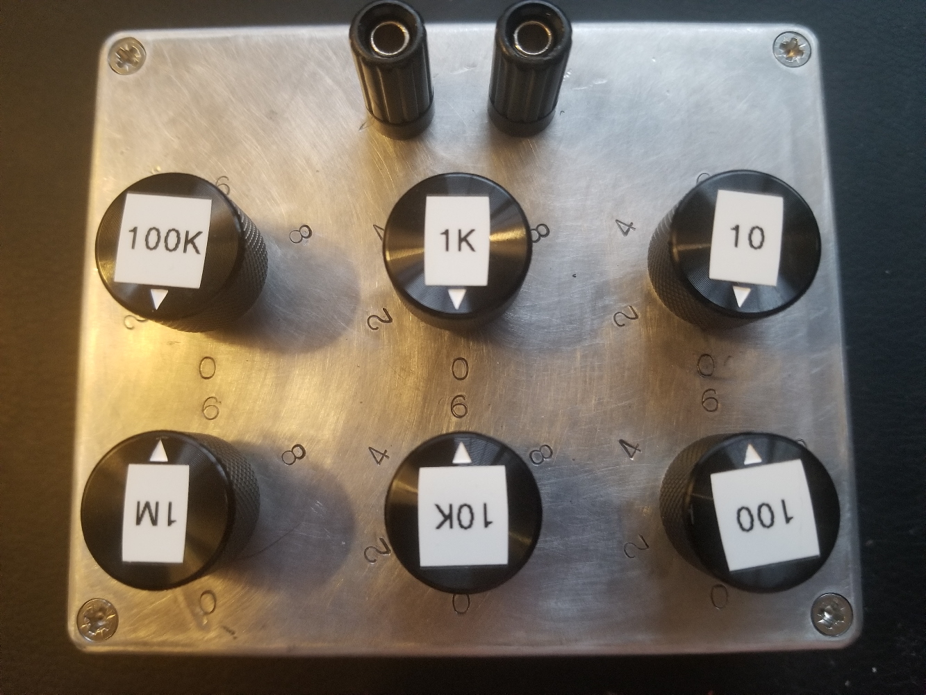
This box has 6 decades from 10 ohms to 1 megaohm meaning it can reach 9,999,990 ohms in 10 ohm steps. All resistors are Vishay metal film, 1/2W, 1%. I'd have liked to include a 10M range but it was omitted in favor of a smaller box.
Design
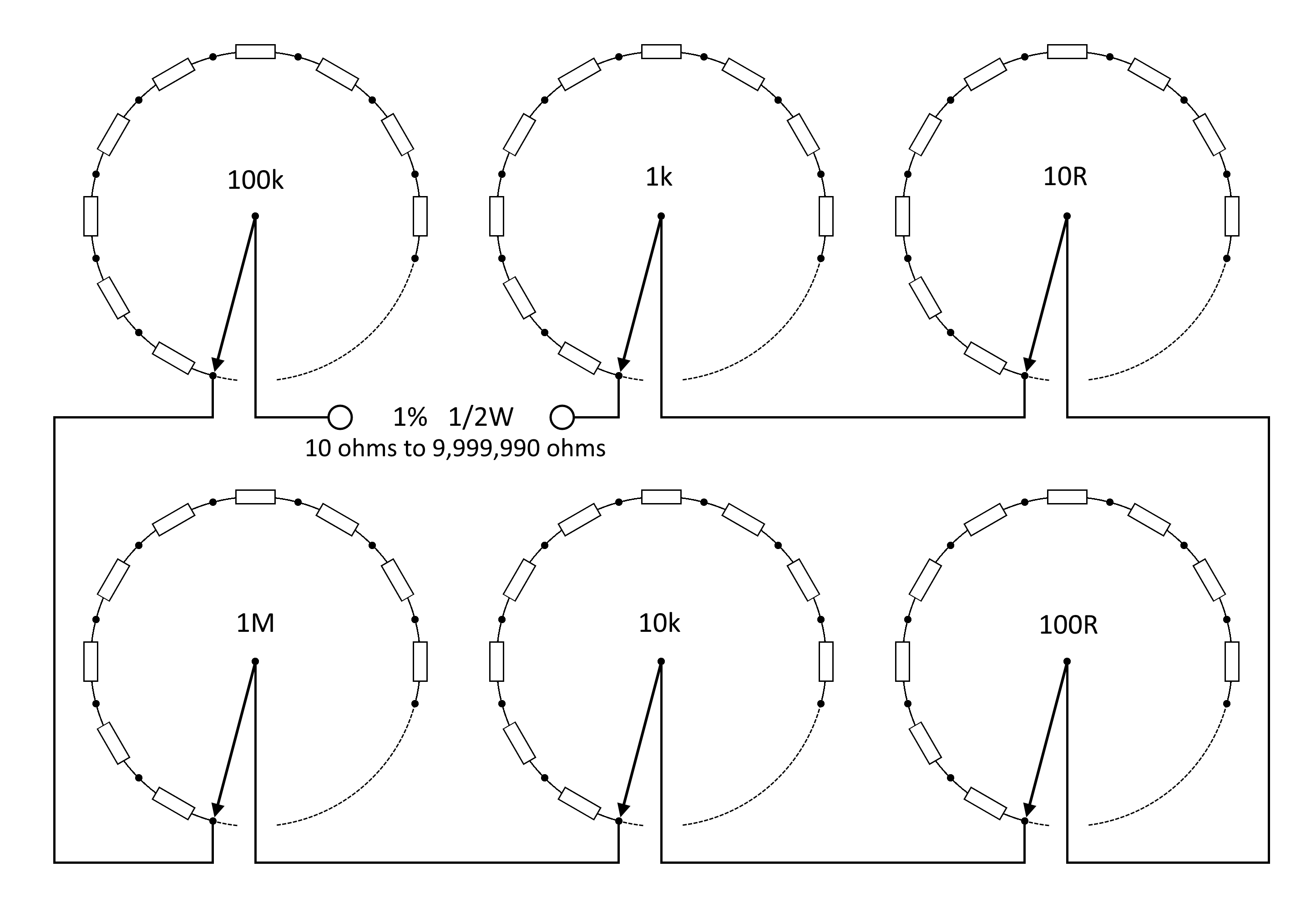
There's nothing clever being done here; this is a bog-standard configuration for a resistance box. Each decade has a resistor ladder which is tapped at each point by a 1P10T switch. An ideal circuit would use 1P11T switches with make-before-break contacts. Such a switch does not exist to my knowledge, at least not unless it's been pillaged from a commercial decade box.
Construction
Chinese rotary switches were used because they're ridiculously cheap. They're very mechanically robust and they offer proper torque and a satisfying clunk when actuated. The knob has no free play. Electrically speaking I'm not very confident in the tribological design of the contacts: it looks like they're just nickel-plated. Oxidation is to be expected in the future, but there's no poor or intermittent contact at the moment.
The switches are joined in gangs of three by a 3D printed frame. This provides anti-rotation and also recesses the switches a bit so the shafts don't stick too far above the case.
Both gangs are fastened to a pretty forged aluminum lid. The lid (and box) are from Bud Industries, pretty much the only supplier of quality enclosures for a fair one-off price. The aluminum is strong but very easy to machine (and file).
The resistors are soldered in a slightly awkward orientation for a reason. It's hard to tell from the picture, but they're standing proud of the switch by about half an inch. The result is that each resistor kisses the bottom of the box when assembled. Kinks are added to each lead to provide some springiness to this contact. In effect we've used the bottom of the box as a heat sink, meaning we might actually manage to get 1/2W out of these resistors without burning them out. Thermal pads could be added to enhance this effect, if I cared enough.
Series connections between the decades and terminals are made by bare 22 AWG solid wire. Objectively speaking this is a bit dumb because it increases the risk of shorts. Aesthetically speaking, however, I think it looks nice.
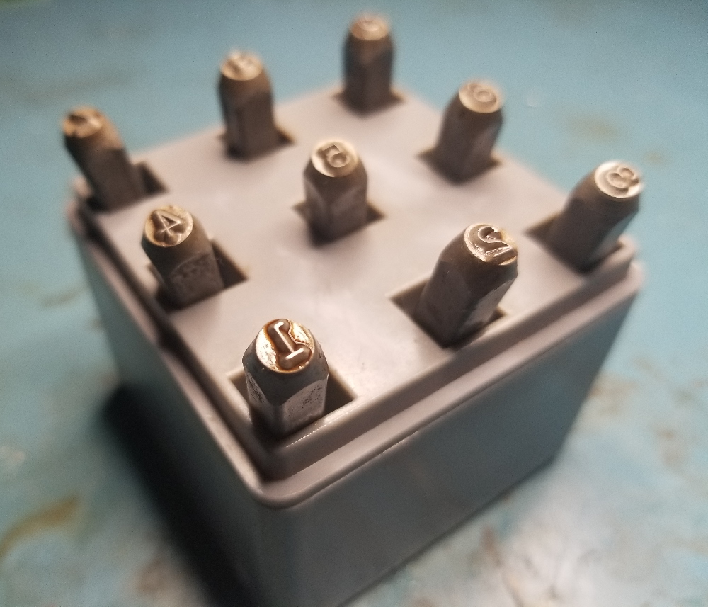
This was supposed to be an easy project. It was, until this point. I bought a set of number stamps to label the switch positions. This was a terrible mistake: the stamps somehow had difficulty marking the aluminum lid no matter how hard I hit them. As a result I had to repeatedly strike the same location, and the stamps refused to land true even when they were pressed into a 3D printed jig. Misstrikes meant that I had to grind and finish the lid in multiple locations, ruining its as-forged look. These were dark days.
I finally compromised and only stamped half of the numbers. This worked fine. I applied a permanent marker to compensate for the weak indents that were achieved with such heroic effort. Decade markings were out of the question - these were made with a label printer as you can see at the top of the post. I'm not too happy about this, but the end result looks good enough.
Total cost was around $56: $20 for the resistors, $18 for the knobs, $14 for the switches, and $4 for the box(!).