DIY Reflow Hot Plate
This is one of those slow-burning projects that limps along for years until self-loathing compels you to wrap things up. I ordered a cartridge heater on McMaster-Carr in 2017. I bought an aluminum plate on ebay in 2019. I finally combined the two in 2020 and actually completed the project in 2021.
Why build a hot plate? I initially envisioned a pre-heater for use in conjunction with my hot air gun. The final product is complete overkill; the plate can be set more than hot enough to reflow a board on its own. The immense thermal mass of 36 cubic inches of aluminum means that boards reflow instantaneously if the plate is already hot (that's not the recommended usage). It also means that the plate stays untouchably hot for hours after turning it off. Despite this, a 1kW cartridge heater brings it to temperature within 2-3 minutes.
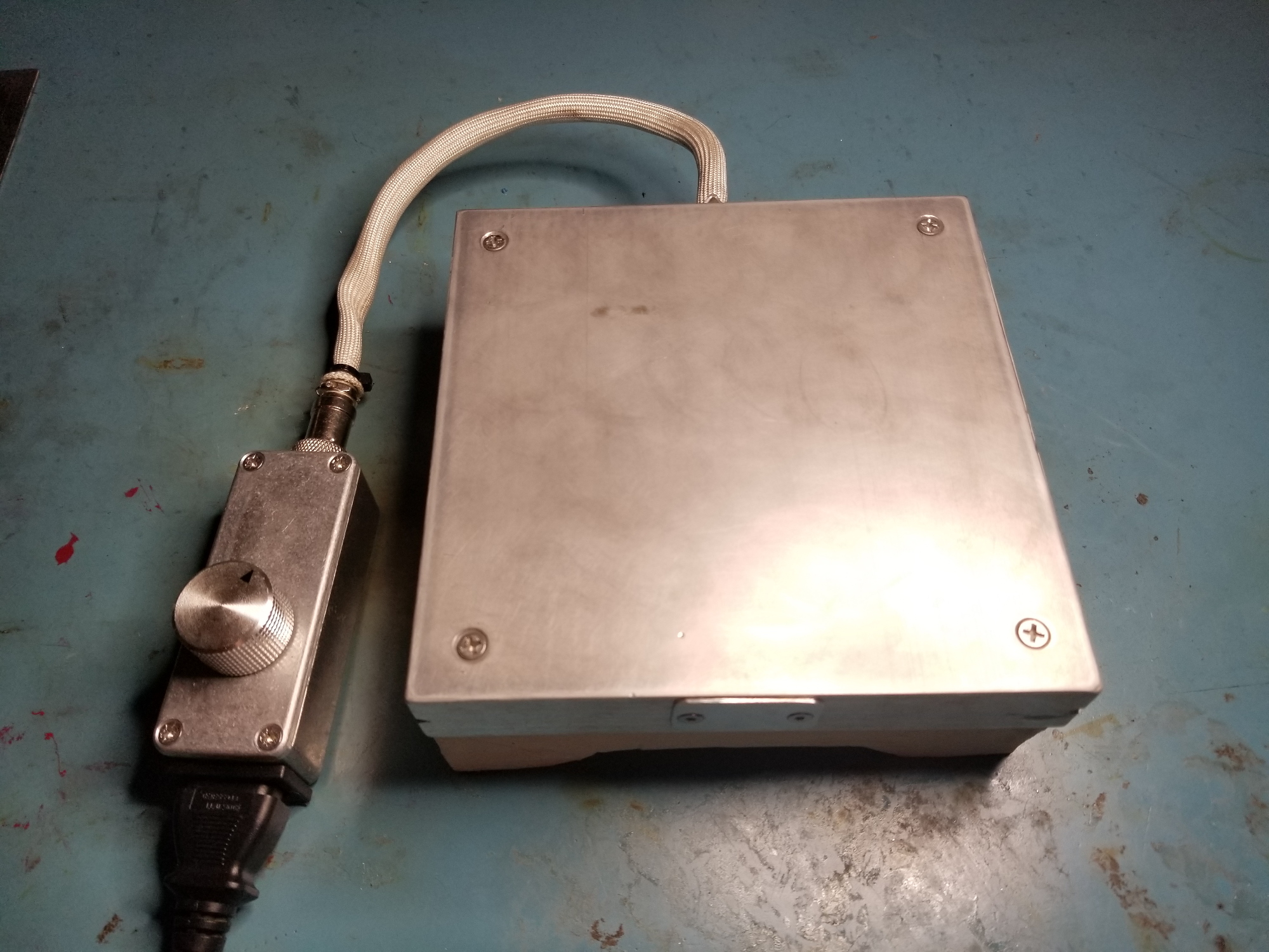
There is no temperature readout because I wanted to keep the controls simple. Feedback is provided by a thermocouple in a deep well. The knob sets a target temperature from 0-500C, but I didn't find it necessary to actually label the setpoints; practical use of this hot plate involves turning the knob up, checking the temperature with my multimeter, and then turning the knob back until it clicks (meaning the current temperature is now the set temperature). The potentiometer has a rotational detent at the minimum setting which turns the hot plate off entirely.
Hot Plate Design
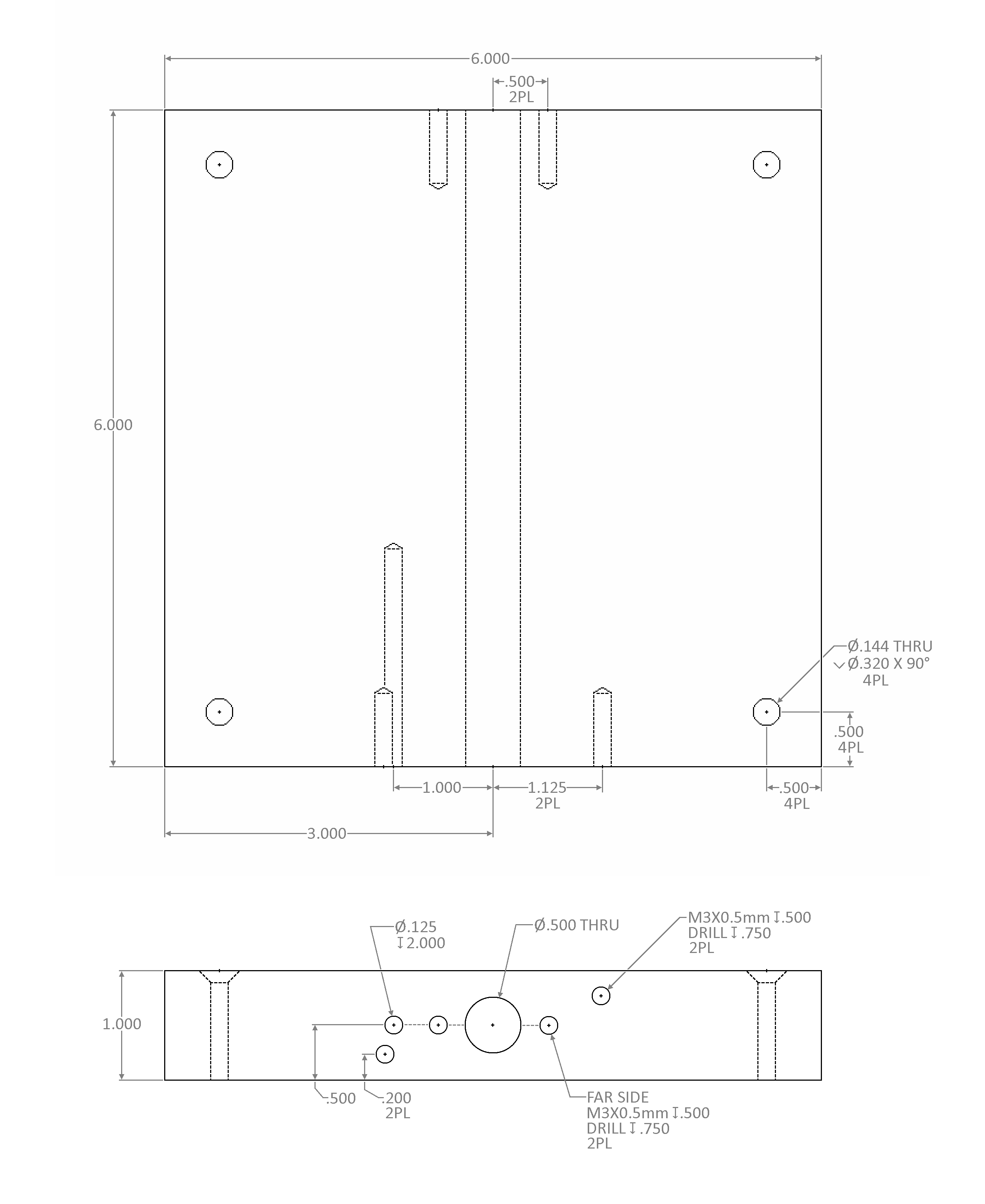
I made the above drawing post-hoc. In reality I drilled the holes wherever I pleased. There are no tolerances because no dimensions are critical - except for the 1/2" thru-hole for the cartridge heater.
The 1/2" hole would ideally have been drilled small and reamed to a precise diameter a few mils less than the actual diameter of the cartridge heater (.494-.498") to allow for an interference fit. An interference fit would be desirable to provide excellent thermal bonding between the cartridge heater and the aluminum plate. I wasn't about to spend $60 on a reamer though, so I "just" used a 1/2" extended drill bit:
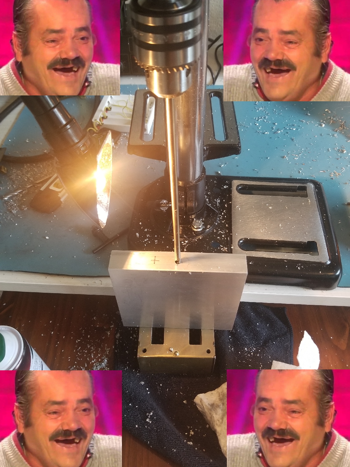
A 6" work piece is too large for my little Harbor Freight drill press; you can see my ridiculous workaround. The hole turned out better than I had any right to expect. Diameter is precisely .500 at both ends, and the exit is less than 0.020 off center. I chalk this outcome up to pure luck. A 12:1 L/D ratio is difficult even with a proper setup. My drill press only has a 2" throw so I had to repeatedly stop and find something to prop the workpiece on. A transformer core worked pretty well in this regard, as pictured :P
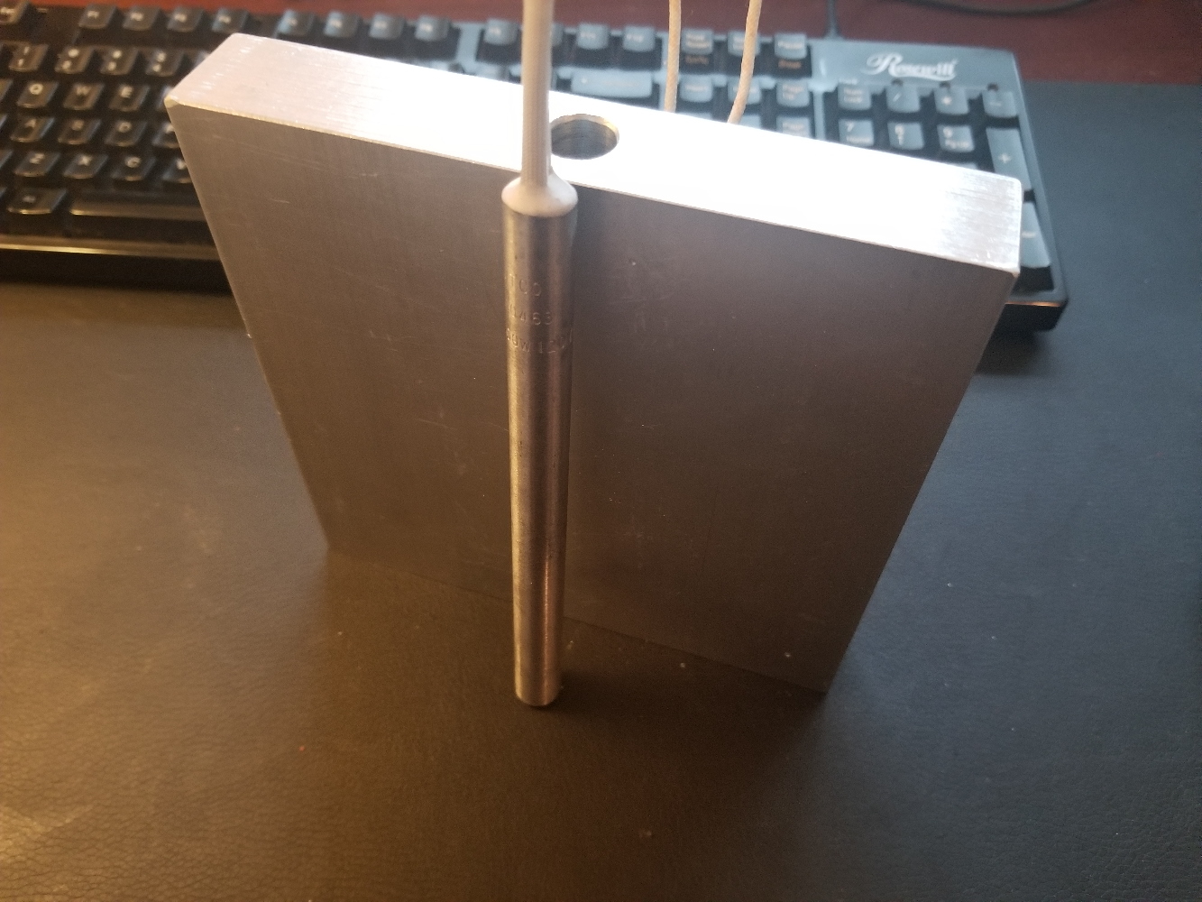
The final hole can be seen here alongside the cartridge heater. The heater is 6"x.500", 1kW, and purchased for around $40 on McMaster. The outer shell is Incoloy. I mentioned above that I'd initially wanted to size the hole for an interference fit. Aluminum (6061) grows much faster than Incoloy though, meaning an interference of around .007" (from memory) would be needed to maintain contact at the maximum operating temperature. That's a pretty aggressive fit; it would be difficult to assemble and it'd put a lot of stress on the aluminum when cold. I think that would cause the aluminum to bow in the middle, meaning it'd need to be flattened after assembly, which I don't have the tools to do. 6061 is also subject to creep at 500C and so the interface would become looser over time (and the flatness would probably change as well).
The rest of the drawing's holes don't warrant much exposition. The four short-axis countersunk holes are size #6 attachment points for the stand/base. The four M3-threaded long-axis holes are provisions for front and rear cover plates, to hold the assembly together. The remaining deeper hole is for a 1/8" type K thermocouple.
Hot Plate Stand
A 500C hot plate obviously needs an insulating base. At this point I'd spent more money on the project than I wanted to (no more McMaster orders!) so my options were limited. I decided to cast a base out of plaster powder, which worked very well. All of the pictures below show the casting process for my first revision. I didn't take any pictures when casting the second and final revision which can be seen at the top of the post. No points for guessing why the first revision didn't work. I'm aware that aluminum has a higher CTE than plaster, but I guess I forgot? Or maybe I was drinking?
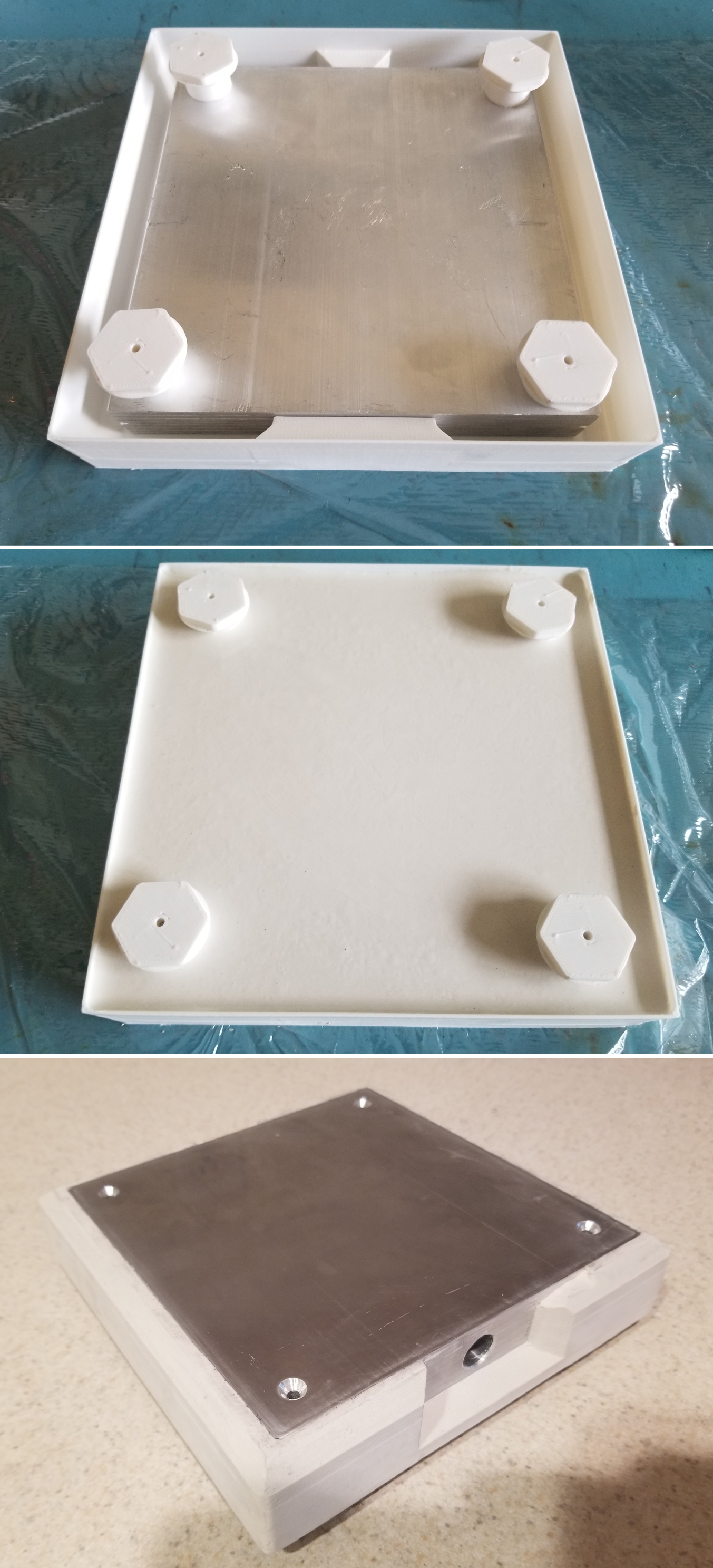
Casting plaster into a 3D printed mold worked very well. I had to carefully burn and cut the plastic away in some locations, which could have been made easier using a multi-part mold or a more aggressive draft angle. Only a small amount of demolding damage was sustained by the plaster, which can be seen in the last photos. I was able to repair it by applying more wet plaster and finishing with a chisel and file. Great success! Until I tested it...
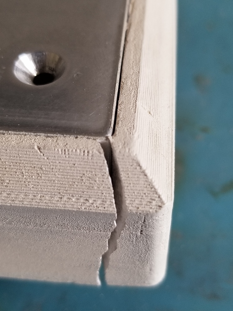
As I said, aluminum grows more than plaster.
I solved this problem on the second casting revision by removing the sidewalls. These were added to minimize natural convection and encourage uniform heating of the plate, but those features didn't turn out to be necessary. The second revision is also flexibly attached using "wave springs" made from wound copper wick. These allow the four attachment points to grow axially without stressing the plaster, and they also provide a tiny air gap between the plate and base which reduces thermal transfer to the base. The result is that the final base doesn't exceed 60C or so even after soaking for an hour. Plaster is soft and brittle so I coated it with a high temperature white spray paint intended for outdoor grills.
Connections
The plate assembly is too hot for electronics. I decided to feed all of the wires out to a standalone control box. That's two heater wires, two thermocouple wires, and a ground strap which would all be quite ugly unless bundled together in a sleeve.
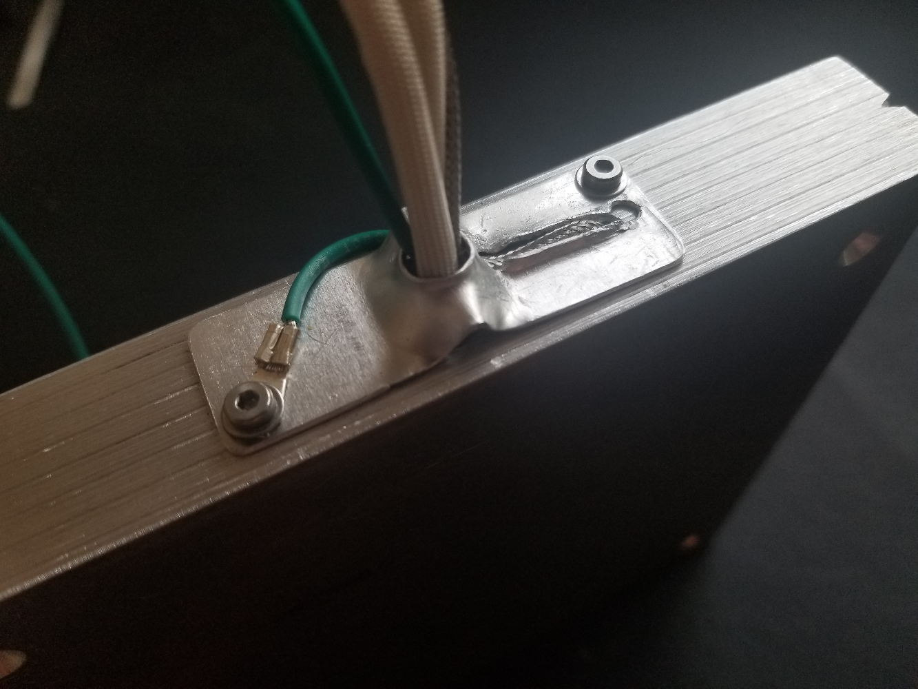
The wires are first brought together by a rear plate that I hand-worked out of 2mm aluminum sheet. I think it looks really nice, and it keeps everything snug. There's a corresponding 2mm front plate to constrain the cartridge heater which is visible at the top of the post.
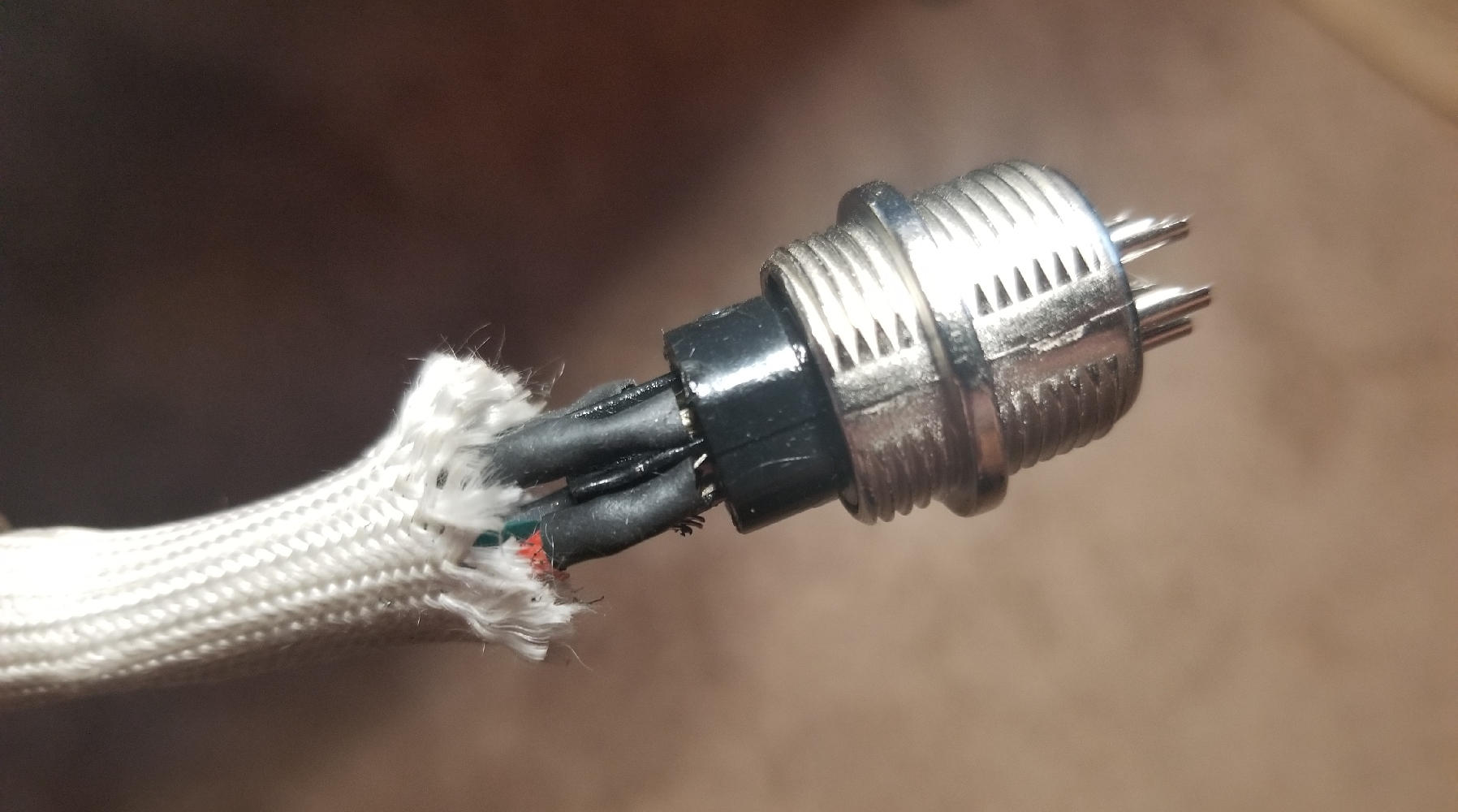
The wires are all fed through a fiberglass sleeve and terminate in a 5-pin "GX12" circular connector. These connectors are incredibly cheap considering the forged zinc frame and decent overall quality. The internal bushing is crap - you must mate the connectors before soldering or else the pins will migrate in the soft plastic. Each pin is only rated for 3A. I summarily ignored this rating and ran 10A through two pins for the heater with no consequences. This design philosophy is applicable for all connectors - the current ratings are specified at contact EOL, maximum ambient temperature, and with every pin at maximum rated current. If that doesn't reflect your application then ignore the ratings and use your judgment (unless you're getting paid, I guess).
Controller
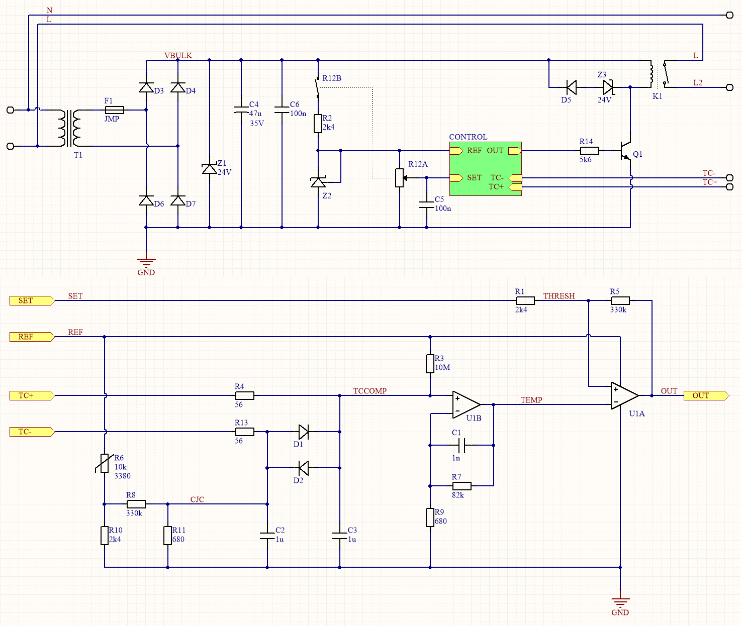
I kept controller simple, but not as simple as it could've been. I decided not to design a mains-referenced triac dimmer because I wanted more ruggedness and because I like the quasi-deterministic lifespan of mechanical relays. The entire control circuit is galvanically isolated by an adorable little Chinese mains transformer from YHDC, meaning no active transient suppression is really necessary.
The hot plate's thermocouple terminates at the circular connector. The signal travels another inch on copper wire before reaching a cold-junction-compensated amplifier. CJC is accomplished by an NTC biasing network located on the control board. This means that the CJC won't be entirely accurate, especially because we'd expect the entire connector to warm up under a juicy 10A heater current. It doesn't really matter though; even a 20C cold junction error isn't critical and I strongly suspect it'll be negligible in practice. The NTC network isn't perfectly compensatory either, it's just adequate and very simple.
Once amplified to 2.5Vfsr, the temperature signal is fed into a bang-bang controller. Due to the gargantuan time-constant of the aluminum plate this controller only toggles every 1-5 minutes despite maintaining a narrow +-10C window. Infrequent toggling means low stress on the relay. It also provides a helpful audio indication which obviates any need for LED indicators :)
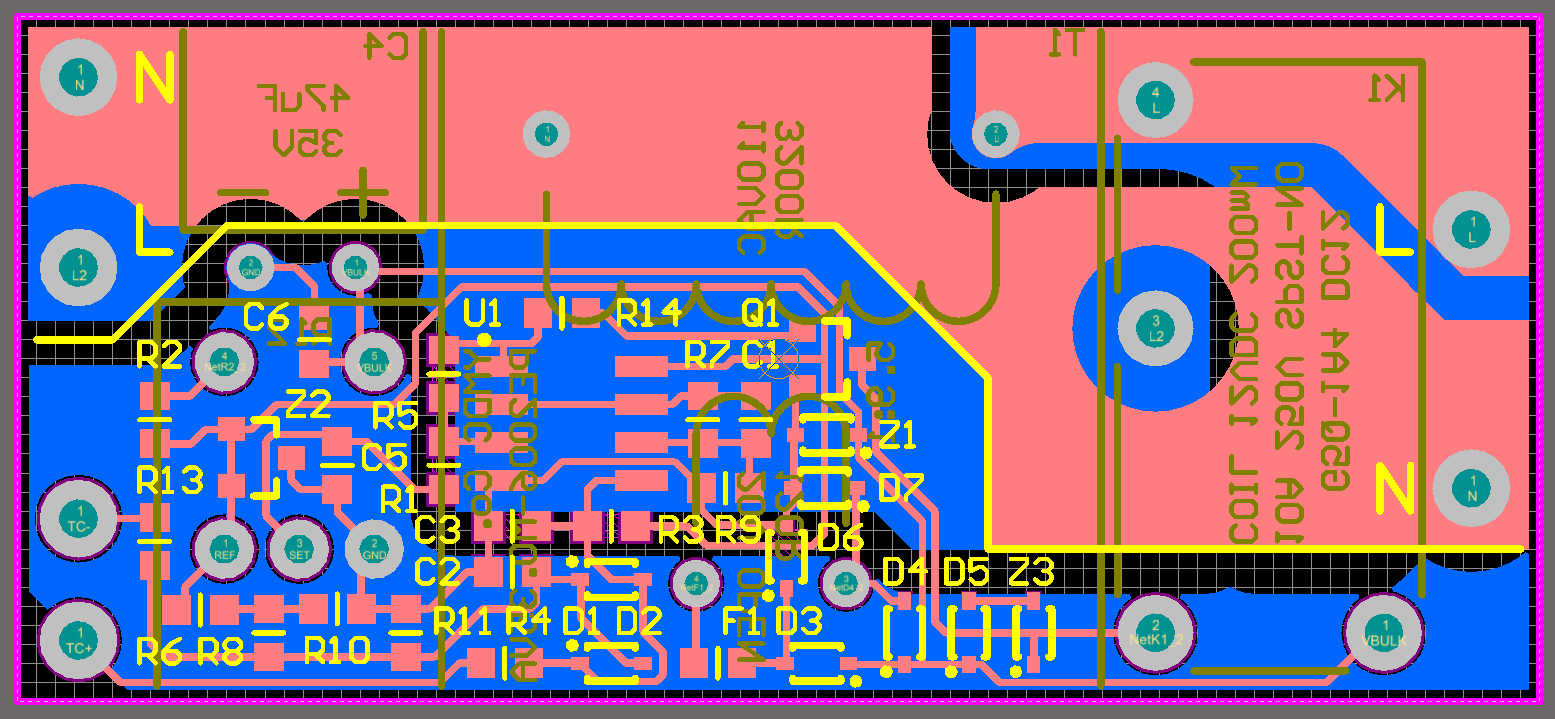
The control board had to fit inside a little ~1x1x3" cast aluminum housing from Bud Industries. I selected the housing for aesthetic reasons, and made everything work around that. The IEC mains input and GX12 output connectors already took up a lot of space, and the through-hole transformer and relay and obscure latching potentiometer really put a strain on this design. I made it all fit though.
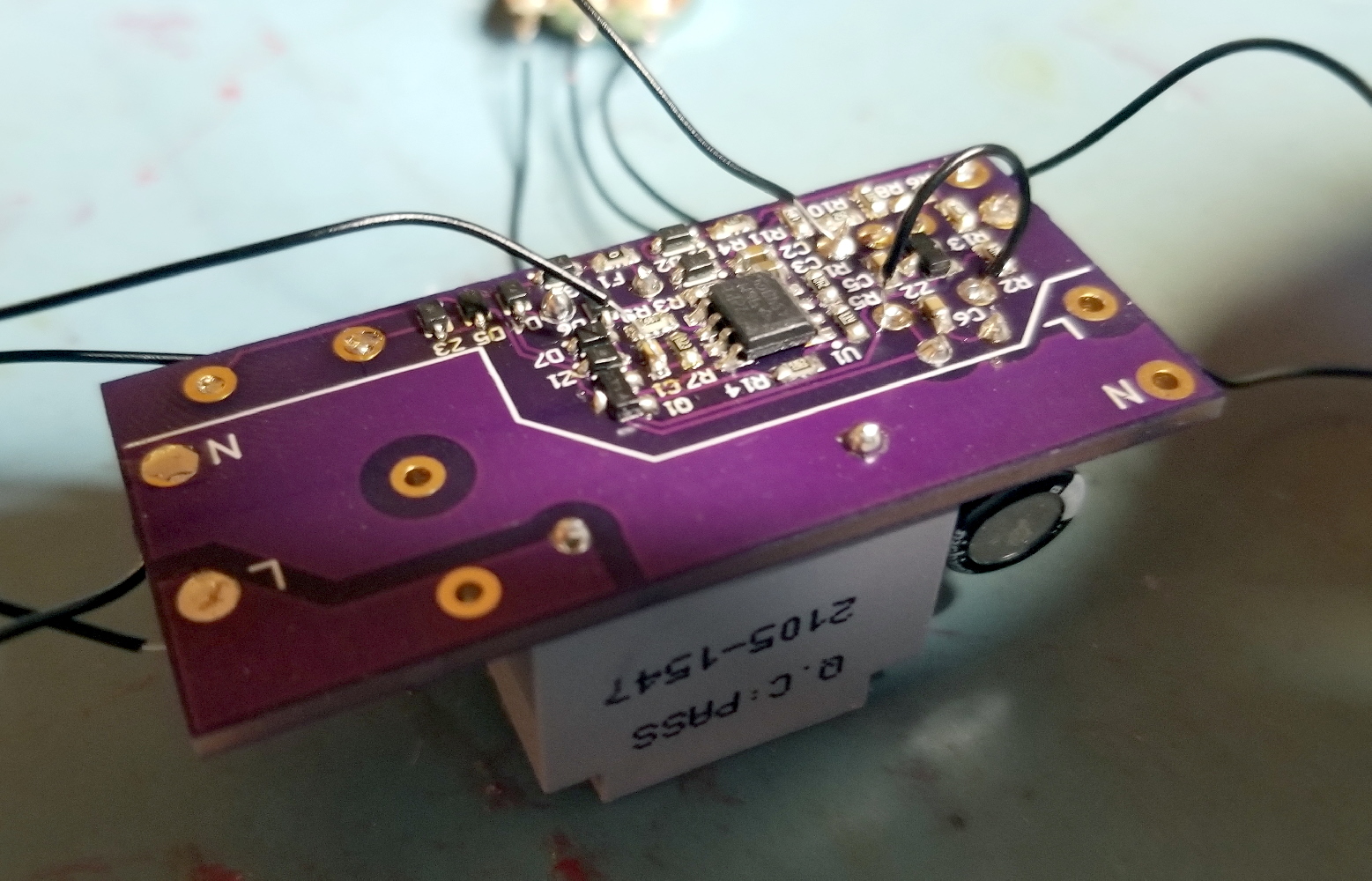
Sadly I was not good at taking pictures of this portion of the project. I only had one picture of the partially-assembled control board during testing. You can see the cute miniature transformer and SMD assembly at least.
What's not shown is the right-angle latching potentiometer. I had an interesting experience with these. I first ordered a pricey one from Bourns, which shipped with a dead switch. I then got one from TDK which got too hot during soldering, so some poorly designed plastic feature in the internal SPST latching switch must have melted. I took it apart and was appalled at the shitty design, which looks marginally functional on a good day. I finally found some no-name Chinese pots which cost a fifth as much and worked well. Have we passed a point where improving Chinese manufacturing quality surpasses waning Western quality, on net?
Results
It lives! The plate is especially useful for soldering tricky components like SMD heatsinks or bottom-mounting inductors. I've also used it for sealing Mylar bags.
I've been asked whether the center-mount cartridge heater results in colder edges. In fact the plate temperature is very uniform because the 1" plate thickness provides very low internal thermal resistance compared to natural convection (about 3C/W estimated for all surfaces). The corners of the plate are never more than 2C below the center.
I was also worried about the flatness of the aluminum plate. I don't have any gage blocks or tools for measuring flatness, so I can't quantify anything, but it has remained perfectly flat (relative to the PCBs) despite sanding to 3000 grit and repeated thermal cycling. 6061 has a solidus of ~580C so stress relief definitely occurred at 500C without ill effect.