Hakko-Powered Fume Extractor
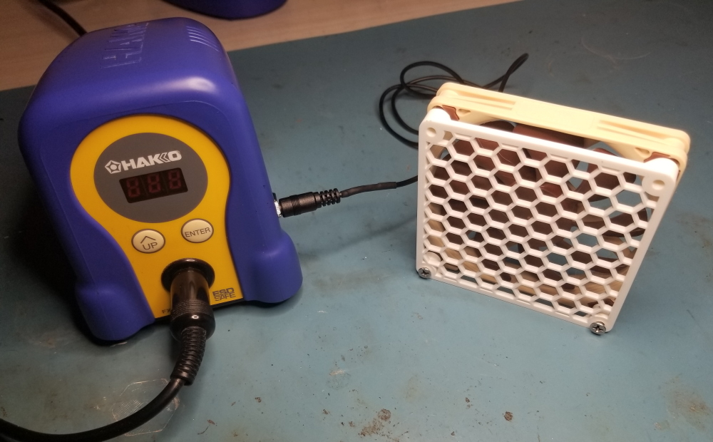
Fume extractors are the sort of equipment that one often "forgets" to use. This is self-reinforcing. The more fumes you inhale, the less likely you are to remember to use your extractor next time. I chose to break this cycle and preserve my remaining brain cells. I've accomplished this by wiring my fume extractor to my iron such that both turn on simultaneously.
A keen eye will observe that I'm not using a real fume extractor. In fact it's just a Noctua fan. The perfectionist may opine that this won't work; doesn't the fan just recirculate the fumes? It does not. The extracted fumes presumably settle or disperse so widely as to be unnoticeable. This is perhaps imperfect but still leagues better than a dense cloud of smoke floating right into your face. In this lab we follow the Pareto principle.
There's no clever engineering at play in this project. The Hakko iron's base station has a 28VAC transformer secondary winding. The power switch is on the primary side, so the transformer is cold unless the iron is switched on. I've tapped the transformer secondary, rectified it, regulated it, and fed it through a 3.5mm audio jack to power my fume extractor. Simple!

The relevant circuitry for the Hakko's control board is pictured above. It's honestly a little disappointing that it uses the same minimalistic topology as crappy mains triac dimmers. That's forgivable, as the transformer will filter out most mains transients. "Ground" as pictured is in fact the highest DC potential on the board; the control circuit runs on a negative supply to avoid driving the triac in its fourth quadrant. This is completely immaterial to my final solution but it was a relevant design consideration.
Our Noctua draws 120mA at 12V. This means that the transformer's rectified 40V (unloaded) is a pretty annoying voltage to work with. Direct linear regulation will dissipate over 3W which is undesirable because the Hakko's enclosure offers poor airflow and because its transformer is unlabeled, meaning I'd rather not draw an extra 3W when the fan only needs 1.4W itself. So I reverse-engineered the control board in the hopes that it would offer a lower voltage to tap. No luck; the bias supply is very weak and otherwise unsuitable in every way.
I considered using a capacitive dropper upstream of a linear regulator. This could be done with depolarized electrolytics that wouldn't need to be too large. Note however that electrolytics can span a 2:1 capacitance range over their working life (compare a new capacitor at +20% to an old capacitor that was -20% when new, and has degraded a further 20% per most datasheets' EOL figure). Designing a dropper requires ensuring adequate output voltage at load and minimum capacitance. At maximum capacitance the dropper's output voltage will be much higher. Downstream, our poor linear regulator will still be dissipating around 2W as it turns out. This defeats the purpose of the dropper. I could always hand-pick the capacitors, but that's just bad engineering.
There are other neat regulating topologies enabled by chips like Microchip's SR-10. These chips are all optimized for mains and aren't suitable at 28VAC. A discrete implementation would be cute but terrible on all metrics.
Woe is me. I gave up and used a buck converter. How inelegant! This drove me to design my own PCB; there aren't any tiny AC-DC modules on the market for this odd application.
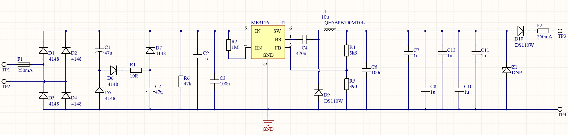
Finding a jellybean buck converter rated for 40V is kind of annoying. I make a best-effort to choose cheap and available ICs. This is counterproductive for prototyping; if I was working for pay I'd have wasted $300 in NRE to avoid buying some niche $8 chip from AD. Nonetheless I found an ME3116 which can be bought one-off for a mere $0.16.
The circuitry is mundane: a mains-frequency rectifier followed by a buck with some protection for the Noctua. The only notable oddity is that the bulk capacitors are wired in a power-factor-correcting topology. This isn't necessary, it's just belt-and-braces to minimize the extra stress we're putting on the Hakko's transformer.
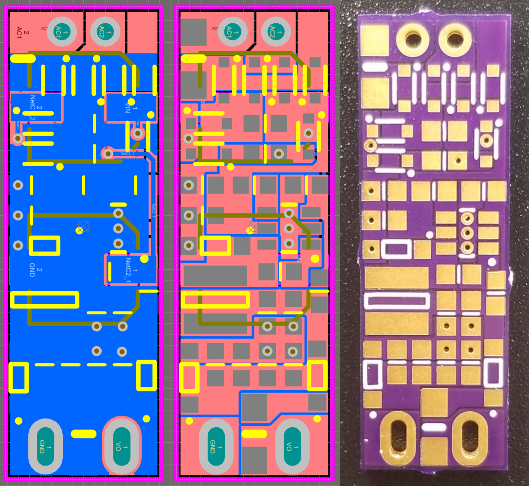
The board layout is also pretty mundane. It's not usually best-practice to place vias on SMD pads. I've never had the slightest issue with it though, and it let me condense the board. The only mistake here is that I misread the inductor dimensions so it's butting up against the buck diode.
Slots are provided on the board for direct mounting to a 3.5mm audio jack, which I used only because I have a lot sitting around. There's not a lot of free space in the enclosure so board size was important. This design fits nicely in a gap between the Hakko's control board and transformer.
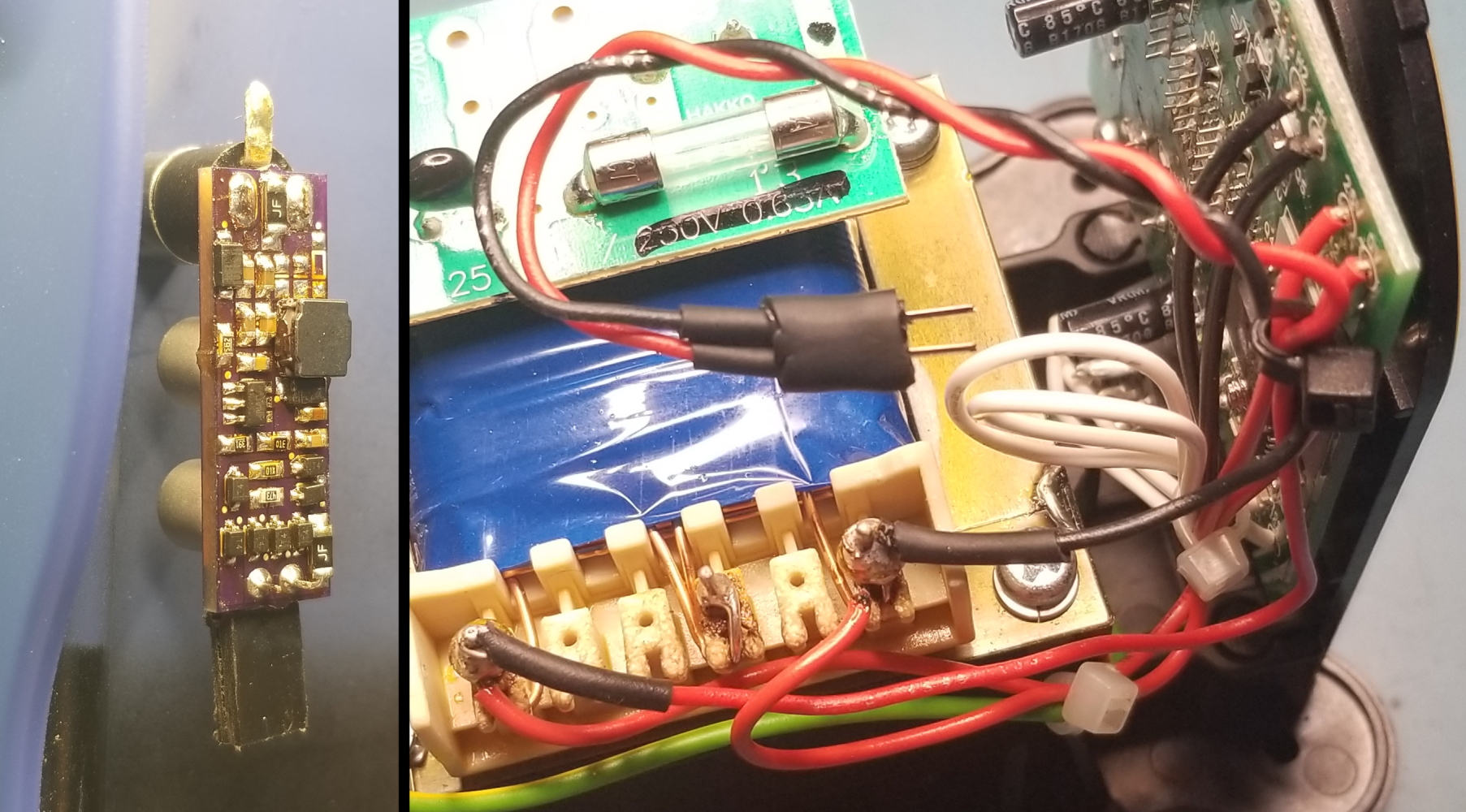
The inputs are wired directly from the transformer's secondary taps. I soldered them on using a hot air gun. It felt wrong to use the iron to solder itself, even if the tip is grounded and the secondary is galvanically isolated.
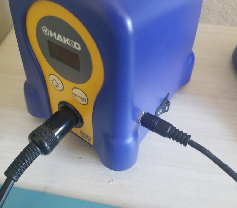
The final result looks pretty clean in my opinion. I used a straight audio plug because that's what I had available, but I've placed an order for a right-angle plug which will be less obtrusive.