Resistance Decade Box
A resistor decade box is the sort of tool that you should build yourself - like a linear bench supply, or a welding table (I guess). In my case this project was long overdue. For years I've had to dig up a potentiometer any time a circuit needed tuning.
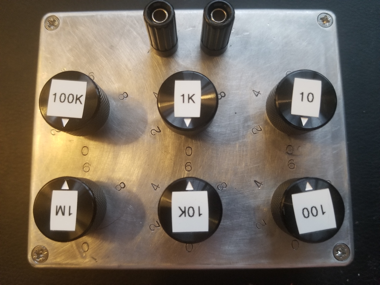
This box has 6 decades from 10 ohms to 1 megaohm meaning it can reach 9,999,990 ohms in 10 ohm steps. All resistors are Vishay metal film, 1/2W, 1%. I'd have liked to include a 10M range but it was omitted in favor of a smaller box.
Design
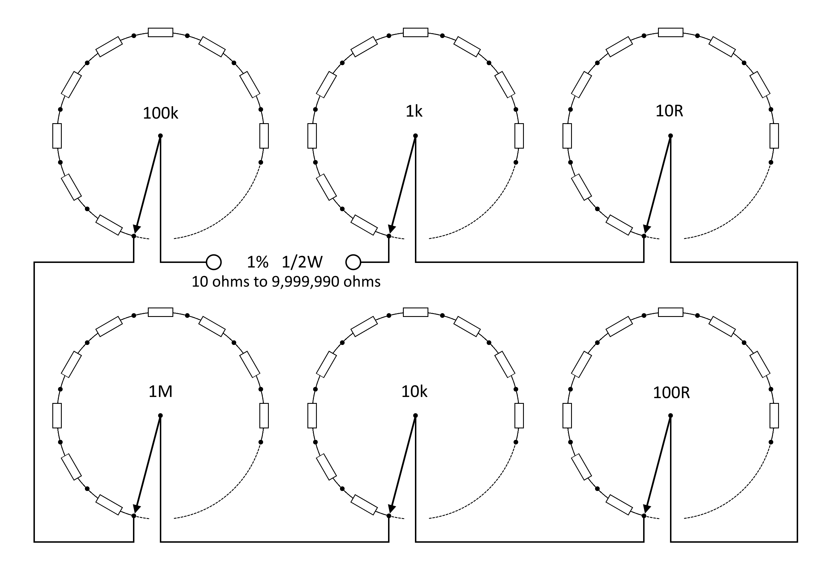
There's nothing clever being done here; this is a bog-standard configuration for a resistance box. Each decade has a resistor ladder which is tapped at each point by a 1P10T switch. An ideal circuit would use 1P11T switches with make-before-break contacts. Such a switch does not exist to my knowledge, at least not unless it's been pillaged from a commercial decade box.
Construction
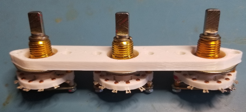
Chinese rotary switches were used because they're ridiculously cheap. They're very mechanically robust and they offer proper torque and a satisfying clunk when actuated. The knob has no free play. Electrically speaking I'm not very confident in the tribological design of the contacts: it looks like they're just nickel-plated. Oxidation is to be expected in the future, but there's no poor or intermittent contact at the moment.
The switches are joined in gangs of three by a 3D printed frame. This provides anti-rotation and also recesses the switches a bit so the shafts don't stick too far above the case.
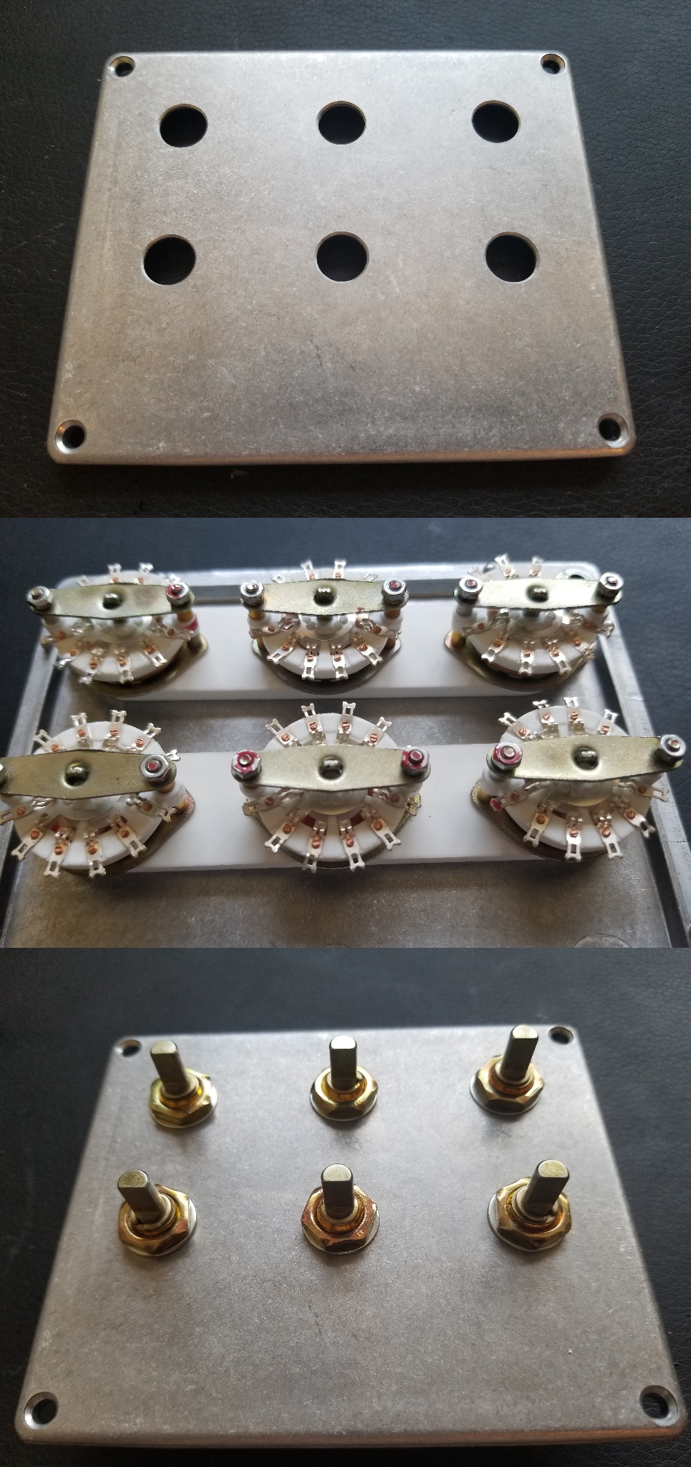
Both gangs are fastened to a pretty forged aluminum lid. The lid (and box) are from Bud Industries, pretty much the only supplier of quality enclosures for a fair one-off price. The aluminum is strong but very easy to machine (and file).
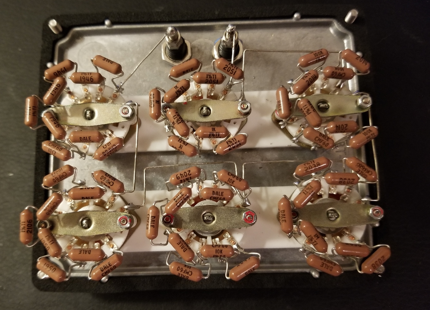
The resistors are soldered in a slightly awkward orientation for a reason. It's hard to tell from the picture, but they're standing proud of the switch by about half an inch. The result is that each resistor kisses the bottom of the box when assembled. Kinks are added to each lead to provide some springiness to this contact. In effect we've used the bottom of the box as a heat sink, meaning we might actually manage to get 1/2W out of these resistors without burning them out. Thermal pads could be added to enhance this effect, if I cared enough.
Series connections between the decades and terminals are made by bare 22 AWG solid wire. Objectively speaking this is a bit dumb because it increases the risk of shorts. Aesthetically speaking, however, I think it looks nice.
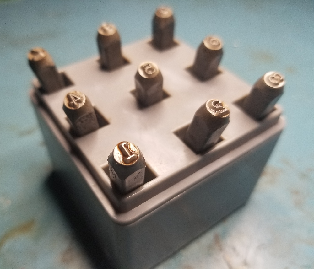
This was supposed to be an easy project. It was, until this point. I bought a set of number stamps to label the switch positions. This was a terrible mistake: the stamps somehow had difficulty marking the aluminum lid no matter how hard I hit them. As a result I had to repeatedly strike the same location, and the stamps refused to land true even when they were pressed into a 3D printed jig. Misstrikes meant that I had to grind and finish the lid in multiple locations, ruining its as-forged look. These were dark days.
I finally compromised and only stamped half of the numbers. This worked fine. I applied a permanent marker to compensate for the weak indents that were achieved with such heroic effort. Decade markings were out of the question - these were made with a label printer as you can see at the top of the post. I'm not too happy about this, but the end result looks good enough.
Total cost was around $56: $20 for the resistors, $18 for the knobs, $14 for the switches, and $4 for the box(!).